I thought I was just going to wire the wall wart directly to the battery terminals. I did not take any of the noise or electrical interference issues into account.
I knew that we would have to devise something to take the battery's place, otherwise it would be an open circuit. That part's a no brainer and an easy fix. It was just this type of thing that I was concerned with. I figured that if was as easy as just splicing into the cord and jumping the battery holder, everybody would be doing it.


![[rofl]](/xen/styles/default/xenforo/smilies.vb/013.gif "ROFL [rofl]") How did I not see 7.62's post & photo when I posted my info above. My bad !!!
How did I not see 7.62's post & photo when I posted my info above. My bad !!!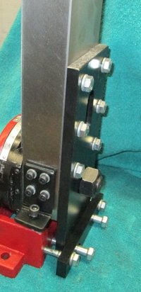
.jpg")
.jpg")

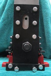
.jpg")
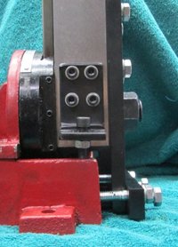
.jpg")
![[smile]](/xen/styles/default/xenforo/smilies.vb/001.gif "Smile [smile]")

") Good Job though! Also don't get oil or coolant on the slides as they will mess up.
Good Job though! Also don't get oil or coolant on the slides as they will mess up.
.JPG")
.JPG")
.jpg")