MaverickNH
NES Member
I just got a WhamBam Flexible Build System - Beaker said it works great on his 3D printer. I had been using Avery adhesion sheets most recently.
If you enjoy the forum please consider supporting it by signing up for a NES Membership The benefits pay for the membership many times over.
The biggest issue I know of is that the wires are tinned and in a terminal block, that's apparently a big nono. Should put them in crimps. Besides that, nothing else is a known fire hazard... But I would personally keep it away from the powderReading about those ender 3 units catching fire.
well, most of smart switches in the walls use same block, and nothing happens.The biggest issue I know of is that the wires are tinned and in a terminal block, that's apparently a big nono. Should put them in crimps. Besides that, nothing else is a known fire hazard... But I would personally keep it away from the powder
Early 8-bit boards didn't have thermal runaway turned on so if a thermistor failed or disconnected it would turn the heat on 100% and stay on.So, I started reading about it - as I left it running overnight ( it still runs) and it runs in a reloading room with quite an amount of powder on a wooden bench. Reading about those ender 3 units catching fire.
If anyone researched that - I just started looking at forums and Reddit- how paranoid should I be about it?
And if it burns - how much actual fire will it be there, it does not look like a lot to catch fire in it except of that filament, that is of course quite flammable.
Just do not want to blow up the house, you know.
well, most of smart switches in the walls use same block, and nothing happens.
i can get crimps for the thick ones, but not sure how necessary that is, as nothing there moves.
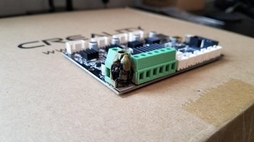
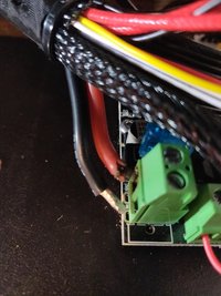
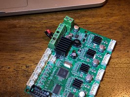
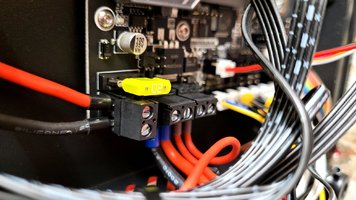
did you yourself do it?It's not an issue with the blocks, but with tinned wires. Solder is compressible, so in a terminal block under screw pressure, the tinned ends will slowly compress, lose contact and then arc. There are many cases of the terminal block melting or charred inside an Ender 3 or similar printer. The wires don't need to move for it to happen. So the recommended practice is to crimp the wire ends.
View attachment 666460View attachment 666461View attachment 666462
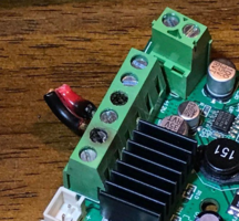
So apparently the popular fix is to solder wire directly to the MOSFET, bypassing the connector on the board. Or better yet, add a separate high-amp MOSFET.those charred ones below are a challenge. the pins that accept the gauge of the wires creality used in there do not fit into the connector they put on the board.
and i am not a fan to solder such wires on a side or trim the gauge of the wire to fit only a part of it into the pin slot
looks like a rather too much effort.As I've said before, it is really easy for this hobby to pivot away from "Making and printing things" over to "Futzing about trying to get the printer to run"
So apparently the popular fix is to solder wire directly to the MOSFET, bypassing the connector on the board. Or better yet, add a separate high-amp MOSFET.
did you yourself do it?
...
those charred ones below are a challenge. the pins that accept the gauge of the wires creality used in there do not fit into the connector they put on the board.
View attachment 666562
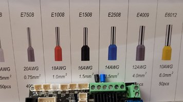
ok, it is my board, pins i tried to use - just checked, were 2.5mm, it did not go at all into that green shit.Verified with my stock 4.2.2 board, it will take 14g crimps without issues.
View attachment 666851
As U.S. Postage Rates Continue To Rise, The USPS Gives The Chinese A 'Free Ride'it really makes me wonder - i still see shitload of chinese crap there, those connectors they sell for $3 with FREE shipping from china.
my kid just had to ship a small box - 4x4x4 to somebody in AZ, a small gizmo he sold privately. the cheapest fare from USPS was $9.
how the hell this chinesium gets shipped for $3 and it is still profitable? is there a loophole somewhere for extra cheap usps fares? a what used to cost $3 to ship before is now $9 and i see no workarounds, really.
to get back on topic - i also bought this enclosure, will see if it`s too ugly to be kept or not. i am not kidding about fire, i had lithium burn - thankfully outside twice, when it burns, it burns well. so, i respect electrical fires very much.
Amazon product ASIN B08D99LSQFView: https://www.amazon.com/gp/product/B08D99LSQF
this is f#cking outrageous indeed, as i just posted a ton of small shit on ebay, and i know how i will be raped sideways by shipping rates there.
Been using this for years on a glass bed. Windex does a good job of removing it.It likely will but why spend the money

Aqua Net Extra Super Hold Hairspray, Unscented - 11 oz
An iconic, cult-favorite hairspray that has been the professional's choice of hairspray for over 50 years. Aqua Net Extra Super Hold Hairspray is formulated to provide greater holding power for hairstyles that demand superior control. The long-lasting forwww.riteaid.com
Yes, an international postal treaty that sets rates for international shipping and gives developing countries special low rates. The value to Chinese countries was estimated at $170 million in 2018.///how the hell this chinesium gets shipped for $3 and it is still profitable? is there a loophole somewhere for extra cheap usps fares? a what used to cost $3 to ship before is now $9 and i see no workarounds, really.///
Another reason I stick with my local makerspace -- usually has that sort of small component in a labeled bin in the appropriate shop.found those exact ones on ebay - an another pointless piece of crap, actually 400 pieces of crap, for $9, when i need only 2.
we used to have an excellent local hardware store that used to stock stuff like that, it died like a 6 or 7 years ago.
F#CK! it was 15 years ago. time flies, damn it.
it was convenient to be able to get such stuff.
Around here Rite Aid is the only place which stocks unscented Aquanet ($3.20 cheap!). I hate going in RiteAid, luckily one can is enough for years of printing.Been using this for years on a glass bed. Windex does a good job of removing it.
i got to say, i am quite impressed with this little ender 3 thing.Another reason I stick with my local makerspace -- usually has that sort of small component in a labeled bin in the appropriate shop.
And if it doesn't, I'll order that 400 piece set off eBay, use the 2 I need, and donate the remaining 398 to the makerspace.
Around here Rite Aid is the only place which stocks unscented Aquanet ($3.20 cheap!). I hate going in RiteAid, luckily one can is enough for years of printing.
I've been using the regular Priline carbon fiber polycarbonate for years. It's no miracle matetial but it seems pretty tough, definitely won't soften in the hot sun like PLA and prints easily. I was suprised how quickly it wore a brass nozzle. I need to try their Superhard as I've always wished the regular stuff was stiffer.i got to say, i am quite impressed with this little ender 3 thing.
i got this filament from ebay earlier in the week
PRILINE Superhard Carbon Fiber Polycarbonate 1KG 1.75 3D Printer Filament, Dimensional Accuracy +/- 0.03 mm, 1kg Spool,Black
and printed it with 260 deg max temp ender 3 does, 95deg on the bed - just the glass bed it came with, no spray no nothing - it did stick fine - it was a small model, of course, and printed it fine, at standard quality 0.2mm layer.
gotta experiment more with it. it takes it some effort to heat up the bed above 80 deg, can be well seen how slow it gets to gain more bed temp as it goes above 80.
i got a hardened steel nozzle on a printer, it should last longer. how does this pristine pc cf stuff compares to the generic PLA+, say, like this one:I've been using the regular Priline carbon fiber polycarbonate for years. It's no miracle matetial but it seems pretty tough, definitely won't soften in the hot sun like PLA and prints easily. I was suprised how quickly it wore a brass nozzle. I need to try their Superhard as I've always wished the regular stuff was stiffer.
I don't know about the PLAplus, but regular PLA is stiffer than the Priline CF-Polycarb, might be stronger but is more brittle (much less tough) and will soften at around 150degF.i got hardened steel nozzle. how does this pristine stuff compare to the generic PLA+, say, like this one:
JAYO PLA+ 3D Printer Filament, PLA Plus Filament 1.75mm Dimensional Accuracy +/- 0.02mm, 1KG Spool Printing Material fit for FDM 3D Printers, PLA+ Blue
?
did you yourself do it?
i just spent a bit of time - as i have plenty of the components, that connector on the top right was not an issue - i found matching crimp pins for that wire gauge, got it done easy.
those charred ones below are a challenge. the pins that accept the gauge of the wires creality used in there do not fit into the connector they put on the board.
and i am not a fan to solder such wires on a side or trim the gauge of the wire to fit only a part of it into the pin slot. so for now i cut off the soldered end, then made a solder blob at the end of the wire only and tightened it into the slot in such a way so screw presses into the wire section with no solder. i think it will be pretty fine, but, will see later about it, may be.
i do not think i have pins with less gauge that would fit into that slot and at same time be reliably soldered to the wire. quite a lousy design there, not sure why they used such a lousy connector on a wire of such gauge.
View attachment 666562
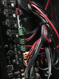
how did it manifest itself? was it stopping printing during the job?has a similar problem with overheating due to the heater bed
btw, looking at the picture - it does not look like you used those ferrules on the wire tips? and all is fine so far?My printer has a similar problem with overheating due to the heater bed. What I did find is that adding a mosfet transistor just before the circuit allows the excess current to go back to the power supply. So I 3d printed a board mount and it sort of hangs off of the motherboard. In the bottom right corner of the inside of the power supply, the mosfet circuit is visible so the heated bed goes directly to that circuit and that circuit either routes to the motherboard or the power supply.
Some 3d printers have higher voltage heated beds and they won't have the same problem. Now with the mosfet I can let it print for days on end with no problems. I also added gcode in my slicer. There's an option to add custom gcode at the end of every job, so I have the heater turned off and the steppers retracted and the bed sticks out to make pulling the part easier. You'd have to look and see what the gcode would look like for a specific printer. This is what I added for mine in Cura, the slicer I use:
; -- END GCODE --
M104 S0 ;set extruder temperature to zero (turned off)
M140 S0 ; turn off bed heater
G91 ;set to relative positioning
G1 E-20 F300 ;retract the filament a bit to release some of the pressure
G1 Z10 ;move extruder up 10 mm
G90 ;set to absolute positioning
G1 X0 Y180 F1200 ;expose the platform
M84 ;turn off steppers
View attachment 666972

btw, looking at the picture - it does not look like you used those ferrules on the wire tips? and all is fine so far?
