-
If you enjoy the forum please consider supporting it by signing up for a NES Membership The benefits pay for the membership many times over.
-
Be sure to enter the NES/MFS May Giveaway ***Canik METE SFX***
You are using an out of date browser. It may not display this or other websites correctly.
You should upgrade or use an alternative browser.
You should upgrade or use an alternative browser.
Finishing 80% AR receiver
- Thread starter 7.62x39
- Start date

It's pricey, but if you want to do 0% forgings, it's the way to go. I'm going to do a 0% after I finish these 80s. I just need to pick up a 1-3/16-16 tap for the buffer tube. I have everything else.
I have one if you need to use it when the time comes.
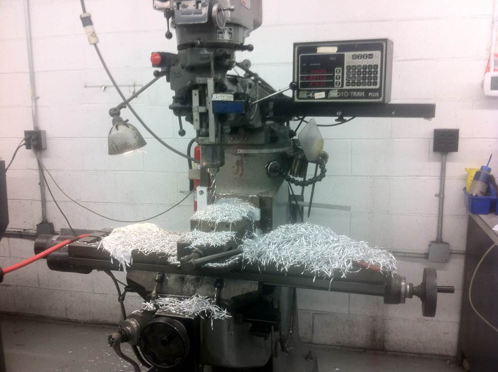
I was at it most of the day, but a lot of time got eaten up tramming the mill and set up. Also I was using a shop vac every few minuets clearing chips, which takes a little longer than just clearing them with air. But I just couldn't see blowing the crap all over the shop.
This was also the very first job done on this mill, so I was double checking everything for accuracy. Now that I know that it is "square" and I've spent a little time getting used to it, I could do the next one in less time.
You don't want to go by me on a time schedule anyway, Building is my hobby, my "Me" time. So I'm never in a rush and am much more interested in the finished product, than how fast I can crank one out.
warwickben
bubba Kalashnikov
Some tips.
Lock you axis use a hammer if you have to lol. Like if your cutting on the x axis lock your y axis.
Use a 2 flute roughing endmill to remove 90% metal . Leaving like .01-.02 for you final cuts .1-1.5k rpm
Switch to a 2-3 flute end mill and cut counter clock wise for you final cut. It will be smooth as glass. 2-3k rpm
Get a old spray bottle and keep spraying the thing with water and if u can find it coolant . Depending on the metal it can be real gummy. Milling through chips isn't a big deal its the gear that causes problems .
Some tips.
Use a 2 flute roughing endmill to remove 90% metal . Leaving like .01-.02 for you final cuts .1-1.5k rpm
Switch to a 2-3 flute end mill and cut counter clock wise for you final cut. It will be smooth as glass. 2-3k rpm
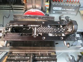
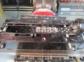
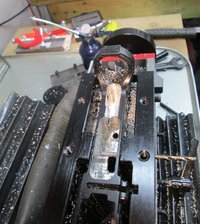
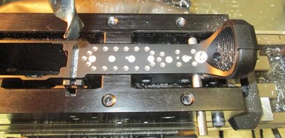
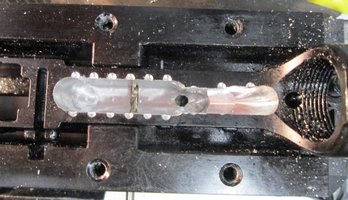
I still need to make the finishing cut. I left it just shy by a couple of thou. I want to make final cut using blueprint vs jig, I will do that this weekend. It looks a little wavy because I did it by the drill press method vs true milling and you can still see remnants of all the 1/8" holes I drilled, they will be gone with the final cut. Although they look a lot worse in the pic than in real life, mostly due to shadows.
Now that I feel that I can trust the mill (and myself) I will do the next one by just milling. without all the holes. I will post another pic when it is finished.
I want to make final cut using blueprint vs jig,
What is this blue print method, like a literal paper guide instead of a jig guide? interesting.
warwickben
bubba Kalashnikov
What is this blue print method, like a literal paper guide instead of a jig guide? interesting.
Lol .... It's not a ak ..
Na like you look at a blue print. And make the part to a print ... U index off a spot like the buffer tube for x. Y should ways be the back jaw since it don't move . Do a bunch of math and figure where to make your cuts etc .
If I had a blue print for a ar . I could build a billet lower on a manual machine ..... But with all the fixtures and crap I'd need to make I'd rather just buy one .... But Im a machinist for a living and after doing it all day long I don't feel like doing it for fun etc ... That's why I make guitars / basses for fun . I use the least amount of power tool.
Didn't take pics along the way - but here's an 80% (black) and a 0% done with no jigs or CNC, just a small manual "mill-drill"...

If anyone needs to borrow the "0%" AR lower tooling (taps, clamping plates, reamers, etc), I still have it.
If anyone needs to borrow the "0%" AR lower tooling (taps, clamping plates, reamers, etc), I still have it.
Last edited:
I did the blueprint no jig method and after I squared the bridgport up they take about an hr ea.
Dave
Dave
can you recommend the size/length/ type end mill you used to do the finishing pass. I have two to do and want to have the proper tooling to finish them properly. drill bits I have . jigs hmm maybe . patience and beer check.
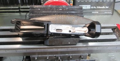
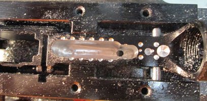
I used a combination 1/4" 3/8" and 1/2". Most of the work was done with the 3/8". You need 1/4" for the trigger slot. I used the 1/2" for the finish cut where it would fit. I need to take a pic of the finished receiver. It came out very nice after the final cut.
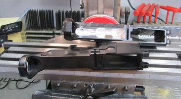
I just started another one, I'm using the true milling method on this one as opposed to the drill press method I used for the one above.
I just started another one, I'm using the true milling method on this one as opposed to the drill press method I used for the one above.
Pocket was mostly by 3/8 roughing cutter with a final pass with a 7/16 4 flute. Trigger hole with 3/16 to final dimension
OK, I'm going IFR on this one, relying on the DROs exclusively.
Let me start with this, I am not a machinist, but have spent a moderate amount time on mills and lathes over the years. Some might say that I know just enough to be dangerous. I am using a layout that I found somewhere on the net, that others have had success with.
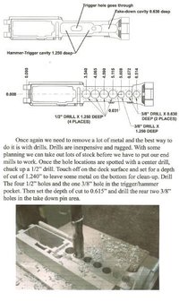
First you need to locate 0,0. everything is done off of this point. The X zero is the centerline of the pivot pin hole and the Y zero is the centerline of the receiver, where they intersect is 0,0. To locate the X axis use an edge finder on the pivot pin. When the edge finder kicks out, 0 your X scale and raise the edge finder up out of the way. Crank your X in an additional .225 and reset to 0. (.100 half dia edge finder + .125 half dia pivot pin = .225) X is done.
To find Y measure the width of the receiver at the FCG pocket area. The AA receiver is .886 so I'm going to use that figure. Set your edge finder on the front of the receiver (facing you, actually drivers side of receiver) when it kicks, set Y axis to 0. Raise the Z up out of the way and dial in an additional .543. reset Y scale to 0 (half the thickness of the receiver .443 + half the dia of the edge finder .100 = .543) To double check, move the edge finder to the back of the receiver (passengers side) it should kick at .543.
The bulk of the material is still removed with drill bits, but with just 7 holes. All of the holes are on the Y zero axis except the hole at 5.608. You need to move the receiver .031 rearward for any operation at that location. I did spot drill the outer holes of the drilling jig just as a visual safety net.
I spot drilled the 7 holes then drilled out the first 5 holes with a 1/4 bit as a pilot hole then out to .500 for the first 4 and .375 on hole 5 with a deck height of 1.245. Remember to add the additional .031 for hole number 5. Do not try to drill out 6 & 7 yet, you will run into the take down pin.
Let me start with this, I am not a machinist, but have spent a moderate amount time on mills and lathes over the years. Some might say that I know just enough to be dangerous. I am using a layout that I found somewhere on the net, that others have had success with.
First you need to locate 0,0. everything is done off of this point. The X zero is the centerline of the pivot pin hole and the Y zero is the centerline of the receiver, where they intersect is 0,0. To locate the X axis use an edge finder on the pivot pin. When the edge finder kicks out, 0 your X scale and raise the edge finder up out of the way. Crank your X in an additional .225 and reset to 0. (.100 half dia edge finder + .125 half dia pivot pin = .225) X is done.
To find Y measure the width of the receiver at the FCG pocket area. The AA receiver is .886 so I'm going to use that figure. Set your edge finder on the front of the receiver (facing you, actually drivers side of receiver) when it kicks, set Y axis to 0. Raise the Z up out of the way and dial in an additional .543. reset Y scale to 0 (half the thickness of the receiver .443 + half the dia of the edge finder .100 = .543) To double check, move the edge finder to the back of the receiver (passengers side) it should kick at .543.
The bulk of the material is still removed with drill bits, but with just 7 holes. All of the holes are on the Y zero axis except the hole at 5.608. You need to move the receiver .031 rearward for any operation at that location. I did spot drill the outer holes of the drilling jig just as a visual safety net.
I spot drilled the 7 holes then drilled out the first 5 holes with a 1/4 bit as a pilot hole then out to .500 for the first 4 and .375 on hole 5 with a deck height of 1.245. Remember to add the additional .031 for hole number 5. Do not try to drill out 6 & 7 yet, you will run into the take down pin.
Attachments
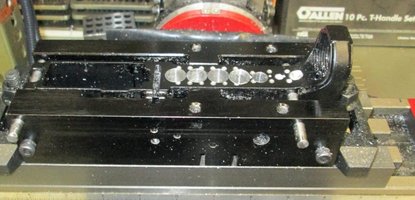
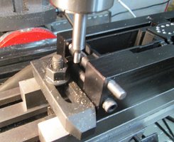
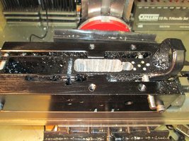
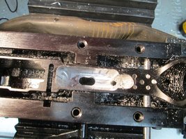
Pic 1) Time to break it down and drill pin holes so I can remove alignment pin from take down hole to be able to work on the shelf area. After pin holes were drilled, I remounted the jig, squared it up and re-established 0,0
Pic 2) Shelf area roughed out. Deck height of shelf is the only thing finished to final dimension, everything else only roughed at this point.
Pic 2) Shelf area roughed out. Deck height of shelf is the only thing finished to final dimension, everything else only roughed at this point.
Attachments
warwickben
bubba Kalashnikov
You want to use 2 flute on aluminum .
If you use 4 flute you run the risk of clogging the flutes up.
If your taking a skim cut you can get away with flooding the part with coolant
You can also skipping drilling so many holes and just do all the milling with a end mill. It you buy a center cut mill you can use it like a drill bit.
When I'm going to do my 80% that's how I'm going to do it . Granted am lazy and if I don't need to change tools I won't lol .
And I find this fun.

You guys work so much cleaner then me lol.
If you use 4 flute you run the risk of clogging the flutes up.
If your taking a skim cut you can get away with flooding the part with coolant
You can also skipping drilling so many holes and just do all the milling with a end mill. It you buy a center cut mill you can use it like a drill bit.
When I'm going to do my 80% that's how I'm going to do it . Granted am lazy and if I don't need to change tools I won't lol .
And I find this fun.
You guys work so much cleaner then me lol.
Last edited:
Wildweasel
NES Member
I will second the 2 flute.
I have both 2 flute and 4 flute center cut end mills, but drilling just removes material so much faster on my little machine. I really only needed to drill 7 holes, I only drilled all those little 1/8 spot holes because I wasn't quite ready to take the training wheels off just yet. lol
I'm sure on a behemoth machine like you have, plunge cutting is the way to go.
I'm sure on a behemoth machine like you have, plunge cutting is the way to go.
Share: