The specs are defined by the rail. Something that interfaces with it will have features designed to match.
er... no? If they matched, it would be an interference fit.. or close enough. If the tolerances of the rail interfered with the tolerances of the accessory, you'd never get them to work.
You could cut the relief with a 45° dovetail cutter, among other methods.
Yea, but you'd still need to clear the other half of the 90° part, and make sure you have the appropriate clearance to the flat top.
This is why I was hoping there was a mill that would have the flat top surface and the critical 45° mounting surface and the less critical clearance.
But I can't find anything like that.
What are you trying to design/make, maybe one of us can help?
I want to make a mount for a Romeo-1 for a lightweight AR-9.
Yes, I know I could probably buy one, but that's not nearly as satisfying.
Plus, it would be nice to be able to mount any arbitrary anything on a rail. Making stuff is fun.
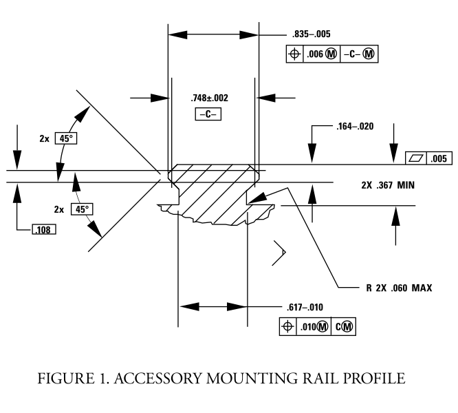
For reference, here's the 1913 rail spec, pulled from Wikipedia (please forgive the transparency if you also use "Dark Mode")
I've got those in my CAD program already, trying to figure out the best order of operations to cut the accessory's mount. Finding mills that are both big enough and small enough is tricky.
I've considered just turning the mill's head 45° or mounting the piece at 45° and using just a regular square end mill to get the "V", and then doing the horizontal surface separately.
For example, if I were designing something to interface with a Pic rail, I would have features that reference the three red edges, and give clearance to the orange edges. Depending on my design, I would make any one of the three red surfaces movable - e.g., the green lines describe the inner surfaces of a clamp.
This is exactly where I was going.
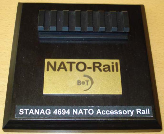
Interestingly, the newest specification (NATO), uses the contact points you show; this is different from the previous Picatinney spec which uses both of the "V" surfaces and *NOT* the top surface.
The new way (the way you and I thought to do it) is more repeatable.
EDIT:

en.wikipedia.org