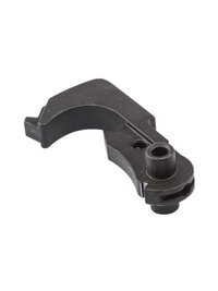
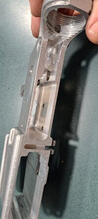
• If you enjoy the forum please consider supporting it by signing up for a NES Membership  The benefits pay for the membership many times over.

More machinists questions.......

What are you using as your zero? I've never worked on an 80% lower. Are the holes already partly drilled? I made thousands of lowers, uppers, gas blocks etc at sig sauer when I worked there.
Front takedown pin hole.

I'll screen cap the CAM setup when I get a chance.
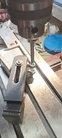
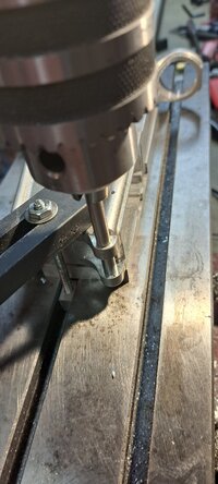
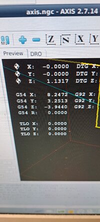
Machine is a Seig X1 micromill that I added steppers controlled by an old computer running LinuxCNC.
With a 180w spindle motor it's not ripping much out of a vice [rofl]
 
If you don't have 123 blocks to mimic @Road_Clam setup then clamp clamp a couple of scraps together and machine them to the same length to use as supports - can even use wood if that'sall you have.
 
I'm not really comfortable with the way the vice is clamped to the table. Could be drawn into the cutter


Based on the pic of the vice set up this would not surprise me.
new vice - jerry rigged down to take some measurements to make decent clamps for this vice.
saw the "this thread is worthless without pictures" post and sarcastically posted the first picture.
However, this mill is way too small to overcome even that setup.
It gets a lot of work done but it does it slowly.
 
Ok, thank you to everybody for pitching in to help the worlds biggest dumbass....

The vise is a problem possibly the problem with tolerance stacking. I always indicate level on the vise from the top of the fixed jaw and it's dead nuts on, however the bed/floor of the vise is off level by about 0.0135 thou. I totally F'd myself with the definition of FIXED!

I'm going to indicate the vise from the bed level and cut the material again with the same setup just to test it...........but other than this test i will cut something like this with the material laying flat on the table in the future.


Thanks guys!
 
The only easy way to fix your out of parallel vise is by shimming. the "low" side. You really need a parallel vice to your table as most of your milling operations is done on parallels placed in your vise. The "right" way to machine a vise parallel is to first machine a sacraficial 2x4x6" block dead flat , bolt the block to your table , then flip your vice upside down, clamp the vice dead flat (locating off the machined block to the bottom faces of the vice) and machine flat the base of the vice.
 
I would remove the vise and check both the table and bottom of the vise for dings and stone the surfaces flat. If that doesn't correct the issue you could dig deeper into the vise and try to correct the surfaces.
 
I'm not really comfortable with the way the vice is clamped to the table. Could be drawn into the cutter.
Properly clamped and zeroed.
Holes drilled - will machine the pocket as time permits.
0.25 deep × 0.050 cuts at 8"/min takes a while... but the machine does the work.
20230219_170225.jpg
 

Attachments

  • 20230219_173711.jpg
    20230219_173711.jpg
    661.7 KB · Views: 13
  • 20230219_173718.jpg
    20230219_173718.jpg
    526.3 KB · Views: 12
  • 20230219_173725.jpg
    20230219_173725.jpg
    673.2 KB · Views: 13
The piece most very likely shifted.

Set it up with step clamps clamps and install 2 dowels in the tee slots as stops.
You will be amazed by how accurate they are.
32 years a machinist. R&D and job shop experience. CNC and and manual.
Lots of good ideas in this thread.
Very good advice here, from Asaltweapon.
This is the way to consistently set up plate steel and square it.
 
32 years a machinist. R&D and job shop experience. CNC and and manual.
Lots of good ideas in this thread.
Very good advice here, from Asaltweapon.
This is the way to consistently set up plate steel and square it.
"the way" ? There is different ways to skin the cat. 4 machinists will have 5 different squaring methods. Whatever the methods, the finished part needs to be in spec to the drawing tolerences.
 
Ok, thank you to everybody for pitching in to help the worlds biggest dumbass....

The vise is a problem possibly the problem with tolerance stacking. I always indicate level on the vise from the top of the fixed jaw and it's dead nuts on, however the bed/floor of the vise is off level by about 0.0135 thou. I totally F'd myself with the definition of FIXED!

I'm going to indicate the vise from the bed level and cut the material again with the same setup just to test it...........but other than this test i will cut something like this with the material laying flat on the table in the future.


Thanks guys!
If your vice is furbared you can mill the backside to fix it.
first step is to very carefully stone your table to be certain there are no burrs.
If your vice can be disassembled to be flat (removable fixed jaw) - disassemble and stone the top surface of the vice base.
Mount the vice base face down and lightly clamp - you want to avoid any distortion and believe me, it doesn't take a lot to distort.
Mill the bottom flat with light cuts and finish with a very light cut. Stone the bottomand deburr.

if the vice has a cast in fixed jaw then you need to make standoff blocks to mount to the table. You'll need a scrap piece the jaw width wide enough to drill and countersink though bolts to the table, and at least 1/4" taller than the jaws.
Drill and countersink the blocks - at this time you only need to clean up the face that will mount to the table.
Mount to the table, knock the corner that will contact the fixed jaw back 0.010" then skim the tops and the face that will contact the fixed jaw. Stone off any burrs.
Now you have a pedestal to clamp your vice to that is as accurate as the machine.

You can do all that work or just shim the vice (but that's not as stable as cutting the base)
 
how does the machine come up with the hole locations ?
I have a full model of an AR lower - From there it's just a couple of steps

1 - make a copy of the completed lower and fill in holes to make it look like an 80%
2 - Create a sketch (drawing) on the faces that you want to work with and "project" the features (holes) on that sketch
3 - In the CAM, select the full lower model as the "model" (finished part) and the one you made into an 80% as the stock to work from
4 - Turn on the sketch you made, add a drilling operation and select the holes you want drilled by clicking the center mark of the holes on the sketch.

If you are turning handles, see the attached PDF - that's how I did my 80%s before CNC.


80% CAM.png
 

Attachments

  • AR-15_Lower_Receiver_Step-by-Step_Machining.pdf
    4.8 MB · Views: 12
I have to check my model - pocket came out the same width as my trigger components so same size doesn't fit.
Like an idiot I broke down the setup before measuring so had to setup again.
And like a bigger idiot put three stupid marks in the pocket by repeatedly hitting jog keys incorrectly.

Had to open the pocket 0.005" to get the trigger to fit properly.
It's sitting half assembled on the bench since I ran out of time.
Currently at the hospital visiting my BIL who is on hospice so prayers for his comfort are very welcome.

Aaron
 

Attachments

  • 20230220_140241.jpg
    20230220_140241.jpg
    475.2 KB · Views: 13
  • 20230220_140236.jpg
    20230220_140236.jpg
    402 KB · Views: 13
  • 20230220_140226.jpg
    20230220_140226.jpg
    684.9 KB · Views: 13
I have to check my model - pocket came out the same width as my trigger components so same size doesn't fit.
Like an idiot I broke down the setup before measuring so had to setup again.
And like a bigger idiot put three stupid marks in the pocket by repeatedly hitting jog keys incorrectly.

Had to open the pocket 0.005" to get the trigger to fit properly.
It's sitting half assembled on the bench since I ran out of time.
Currently at the hospital visiting my BIL who is on hospice so prayers for his comfort are very welcome.

Aaron
I'm sending my prayers
The good Lord will make him get back on his feet healthier
 
I have a full model of an AR lower - From there it's just a couple of steps

1 - make a copy of the completed lower and fill in holes to make it look like an 80%
2 - Create a sketch (drawing) on the faces that you want to work with and "project" the features (holes) on that sketch
3 - In the CAM, select the full lower model as the "model" (finished part) and the one you made into an 80% as the stock to work from
4 - Turn on the sketch you made, add a drilling operation and select the holes you want drilled by clicking the center mark of the holes on the sketch.

If you are turning handles, see the attached PDF - that's how I did my 80%s before CNC.


View attachment 723257
something I have zero experience with. I was playing around with some free software linked over at one of the machinist forums , going a little crazy just trying to figure out basic shit. Since I really dont have any machines with any CNC/DRO capability I just gave up. This smithy is not a good mill/ Maybe drilling. Again since the lay off no time to f*** around on the lathe plus my tool boxes are in the way. I think my shed sank 2 inches since I put all my tools in there.
 
something I have zero experience with. I was playing around with some free software linked over at one of the machinist forums , going a little crazy just trying to figure out basic shit. Since I really dont have any machines with any CNC/DRO capability I just gave up. This smithy is not a good mill/ Maybe drilling. Again since the lay off no time to f*** around on the lathe plus my tool boxes are in the way. I think my shed sank 2 inches since I put all my tools in there.
Depending on what your mill vice looks like, I might have an "upgrade" for you.

Turning handles isn't all that bad
Drill out the four corners then it's just cleaning out the middle.

As far as jobs - check USA Jobs.
Government jobs pay okay but the stability helps a lot
 
Depending on what your mill vice looks like, I might have an "upgrade" for you.

Turning handles isn't all that bad
Drill out the four corners then it's just cleaning out the middle.

As far as jobs - check USA Jobs.
Government jobs pay okay but the stability helps a lot
Cool , my mill vise sucks its more of a drill press vise.
The entire mill has its issues.
Lots of slop when trying to make a cutting pass.
When I can get to it again I will do a vid
I did pick up a 4 jaw chuck nut I need to make a plate. The way the mill is behaving thats going to be a tough project

Its a 4 or 5 inch bison 4 jaw made in poland. New in box . Was gifted to me.
So I need to adapt a plate that bolts to the 3 hole flange on the spindle and takes the 4 bolts from the front of chuck to that.
I dont have a accurate way to lay out the holes. Or any scrap bog enough to even practice on.

226A4052-81AF-46B1-9521-817190E9C422.png 03180025-6E73-40ED-9E49-9EB1FD00D4D9.jpeg
 
Last edited:
Im jealous, Bison chucks are the Rolex's of chucks . your starting to find the limitations of
"3-1" type machine configurations. Does your mill have a good functioning column lock ? Problem in with a column theres always the potential for lack of a rigid locking of the head. The other issue that comes to mind is rigid bolting of the machine , i know you have it out in your shed, do you have the machine bolted down to a sturdy table ?
 
ok, here's a machinist question.... any of you guys make AR FCG parts?
you know how modern viking type bros have fancy hammer pendants around their necks?

i've been kicking around the idea of an M16 hammer, probably in stainless... something jewelry friendly...

of course, it wouldn't need the slot in the bottom down by where the hammer pin goes through, and it wouldn't need the bushing part where the spring rests on either side of the pin hole...

anyone have these drawings queued up in a machine already?

since i don't have thousands of dollars to spend on a one-off custom piece, failing all that, what would it run me for a $16 off the shelf m16 hammer to have the spring bushing neatly milled off and to have the thing re-phosphated?

being of Irish descent, i wouldn't wear a Mjolnir.... but i'll wear my own hammer symbol :)
 

Attachments

  • LR_34k-400x533.jpg
    LR_34k-400x533.jpg
    8.8 KB · Views: 7
  • mjolnir-amulets_1024x1024.jpg
    mjolnir-amulets_1024x1024.jpg
    60.4 KB · Views: 7
Last edited:
Back
Top Bottom