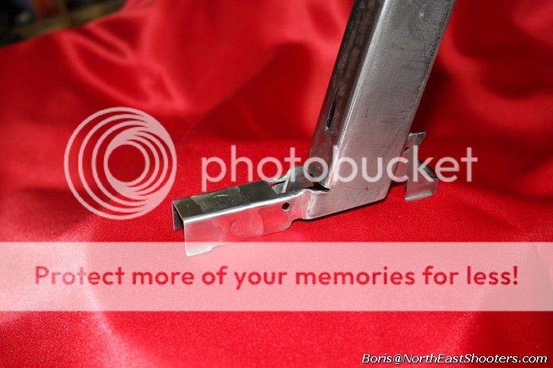
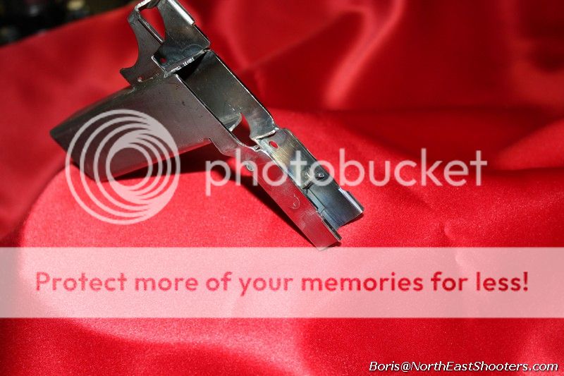
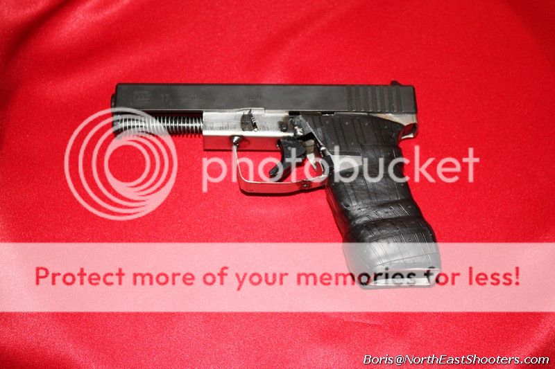
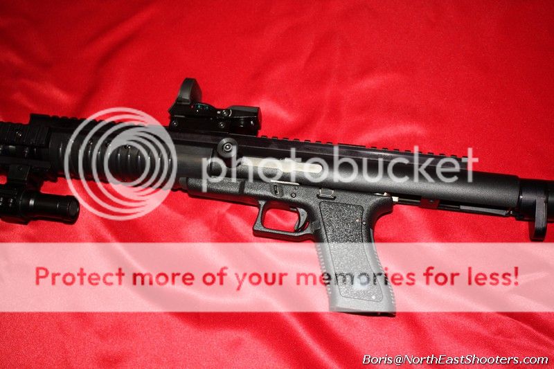
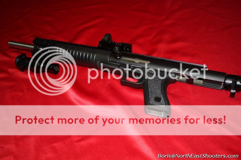
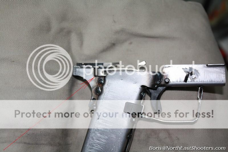
Iron Glock

Boris

Son of Kalashnikov
Joined
Jan 14, 2011
Messages
21,353
Likes
25,314
Location
Back from Motherland
Feedback: 22 / 0 / 0
IANAL, but all activities described herein are 100% legal in accordance with both Federal and state laws. If this shocks or disturbs you, please move to any one of the already existing communist shitholes ... or/and Kalifornia. You deserve neither liberty nor security.

I want to give a special thanks to Dark Lord Marsha Cloacaly and the Soviet Rupublic of mAssucktaxachussetts (with fake "Indian" Lizzy on its seal) for making it all possible. Without you, I'd just buy a gen4 Glock.


"Rifles do have a place in the survivalist’s arsenal, and a very important one. But you have to understand that 90% of the time, the handgun will be the weapon you have available when you need one."
Thoughts On Urban Survival by Ferfal

Das Eiserne Glock​

The Iron Glock​

p01.jpg


Why Glock ?

History of Glock

How Glocks work

Building your Glock

- Fore-piece, steps F 1 - 3

- Aft section, steps A 1 - 3

- Mid section, steps M 1 - 3

- Joing, steps J 1 - 7

Finishing up

- Mech-Tech upper for your Iron Glock frame

Common Issues and Problems

Vids


List of updates

DateStepsWhat's updated
7-8-13Step M2Added pictures on welding the grip together
7-10-13Step F3Added jig description for marking the hole
7-12-13Step F1Added pics and dimensions for fitting the forward piece-rails
7-26-13Step J5Added pics and dimensions for fitting the slide stop
8-14-13Finishing Up + MoviesMech-Tech in finishing up section + more vids of shooting with Mech-Tech upper
10-08-13J5Added guides for all three kits, where to cut the slide stop slot and distances.


Why Glock?

Since the dawn of Man, at any time, in any nation, people who bear arms freely without infringements were called FREE MEN. Since the dawn of Man, at any time, in any nation, people who were restricted or banned from bearing arms were called SLAVES or by any other name.

I started to look for a BIY pistol for the time when zombies are not quite roaming the streets yet, but currency already has little value and we have a bunch of crooks running .gov. In other words, cheap, realiable pistol capable of variety of calibers with parts that could be found easily and could interchange. ... also it can't be made out of aluminum (like a lawn chair or AR)

My choice fell on Glocks, the plastic AKs of the pistol cosmos. Glock is the opposite of any typical German gun: simple, loose tolerances making it reliable by even Russian standards, most parts interchange between models and it sucks to shoot. Glocks have many advantages. There are so many of them everywhere that I often check my Krapfen Strudel for Glock parts after I take my morning dump. Several aftermarket companies work day and night making a whole bunch more. Hi cap mags are fairly cheap and very common, but the best part is that having one frame you can switch the slide in a few seconds and shoot 22lr, 9mm, 40 or 357.
p49.jpg

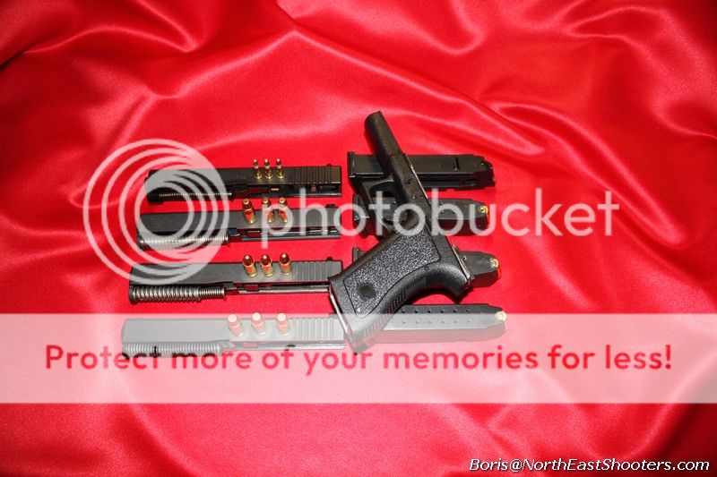
If you use terms for pseudo-firearms, ... like ARs, Glock has an upper or the slide that could be changed quickly, like 2 sec quickly without breaking any aluminum hinges (aluminum like in a lawnchair). This upper-slide comes in variety of calibers. The "lower" frame is a piece of plastic that grips Glock's LPK. Amazingly as always, only the plastic frame is considered to be the firearm. LPK that is FCG and few other random bits are typically $75 and are not regulated. Slides are not regulated either and can go anywhere from around $250 and up. With mAss Glock prices for gen 4s sailing north of $800, this is a very attractive option.

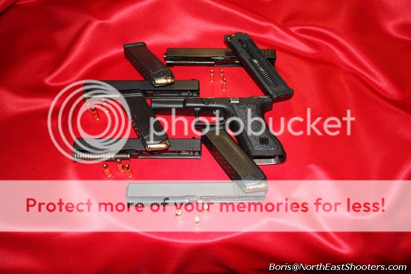
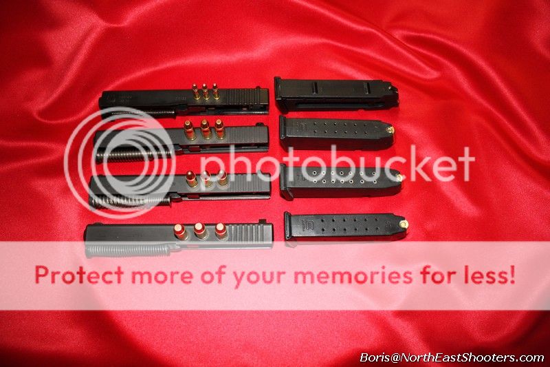
four calibers
p50.jpg

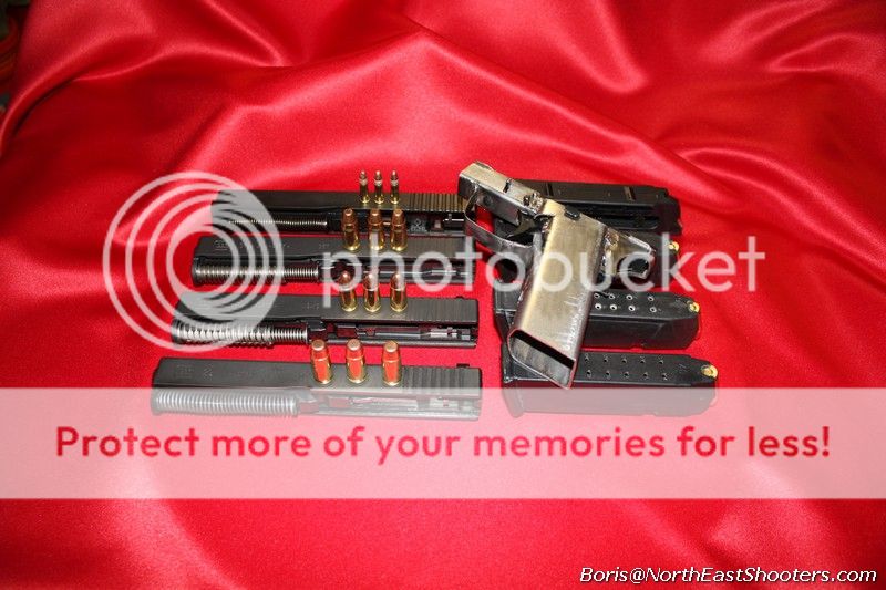
one "glock" to shoot them all

p51.jpg

... Das Eiserne Glock!

p52.jpg


History of Glock

Gaston Glock started his career designing curtain rods. He stamped this fruity shit on a Russian stamping press that supposably was left by Kalashnikov himself when he was kicking ass on his tour through Europe. Over the years, vodka vapors used in lubrication and the sheer Awesome radiating from the press kept accumulating until it reached critical mass and made Gaston marry huge boobs with a chick that were less than half of Gaston's age and then pay a ton of money to design Glock17. G17 combined two awesome concepts: St. JMB's locking barrel design and Kalashnkov's principles of manufacturing cheap, reliable guns. It's like US made vodka: it tastes good while making you a filthy capitalist pig in the process.

While Glock has become an iconic firearm, Gaston's skill as an engineer are probably on par with St. JMB's butler. However, his talents to find people to design, market and sell the gun is without a doubt laudible. The only two firearms that every US journalist knows is either an AK or a Glock. Now you can build both ... from the same shovel.


How Glocks work

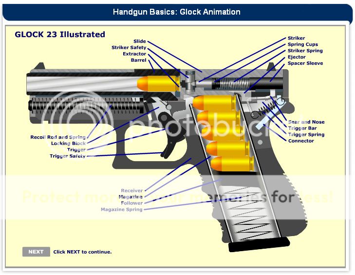
As I have mentioned, Glocks use St. JMB's design to lock barrel in the slide, making the slide pretty much a firearm in itself as it also houses the striker. Frame serves secondary functions like holding the mag, extractor and FCG. The rails guide the slide back and forth. "Locking block" actually unlocks the barrel and has nothing to do with holding it locked.

For those who want to learn how Glocks work and play with it in the safety of your mom's basement, there is an awesome interactive Flash app that allows you to take a closer look how components work, fire the gun etc. It's located on Genitron's website: (some virtual licensing may be required to fire virtual guns)

Glock Pistol Animation

Here is a screenshot of the app:
genitron.jpg~original

don't worry about this being Glock23 ... 23, 32, it's the same shit in different dimensions.
 
Last edited:
Building your Glock

Achtung: check your local laws and make sure that you can legally assemble and possess a high capacity pistol. Also check related laws, you may not legally drink on Sunday, vote or have sex with a person of different race.

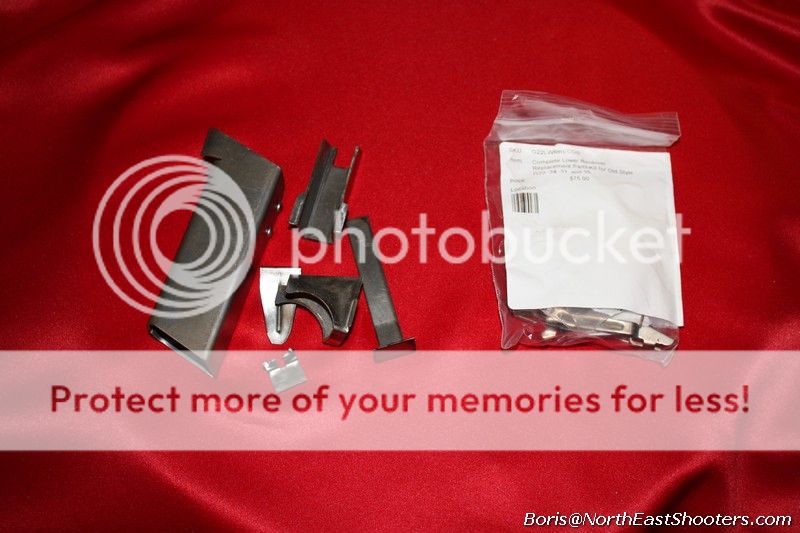
Here is everything you need to assemble the Iron Glock frame:

p53.jpg

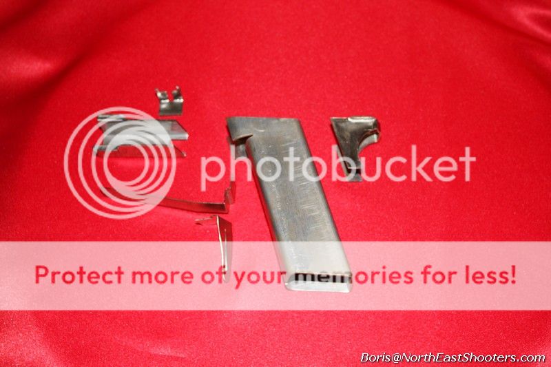
I am starting with the Marigold-1 kit from A-r-m-u-s.com It's a collectionAof random bits of bent sheet metal that could be made into a sculpture of a marigold, a kitten or Diane Feinstein's twisted brain (althogh I'm not sure that she's got one ... well at least not in her head)


kits.gif~original


I know, you just need an excuse to say to yourself that you can never build a real pistol, that "your hands are tooled for a dick only" and cry yourself to sleep. Well, guess what, this is a kit build and therefore you can build exactly the same pistol (minus unicorns or ivory grips, I contracted child soldiers to kill the last elephants in Africa)

If you have questions ask, if you need more pictures ask. If you live within a reasonable driving distance and need help to build it I will come and drink all your vodka, puke everywhere, scare your neighbors with loud music and hide stripper's panties in the places where only your wife will find them ... but we will build damned pistols and you'll like it.


p54.jpg

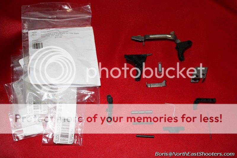
Also, I need a Glock LPK lower kit. These are available from a lot of different places. Get an older 22 replacement kit and stay away from 17 kits. Although they are almost identical, 22 is much more beafy and can cycle both .40 and 9mm., while 17kit may not.

shit, I know people will ask this, just ****ing google "glock complete lower receiver replacement kit" and order an older kit for G22 (usually works for 35 and 31)

p55.jpg


Step F1

Smooth all the edges and burrs.
Keep in mind that most Glock parts are plastic and sharp metal will shave that plastic. Make sure that places where plastic rubs are smoothed out with fine grit sandpaper or polished ... or

pb.jpg

... have a beer

Grind the rails.

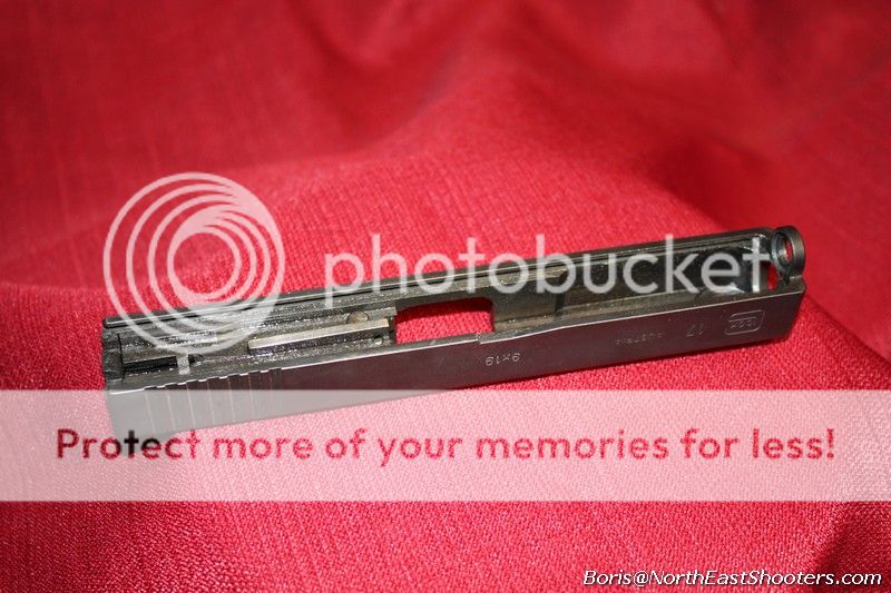
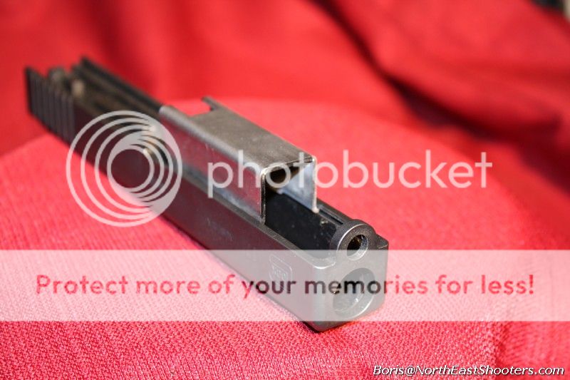
Let's look at the actual Glock slide:

p87.jpg

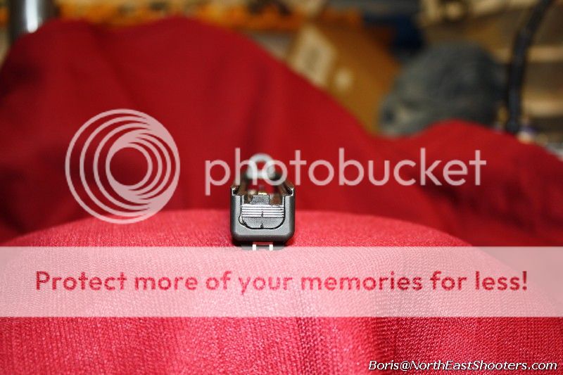
and from behind

p88.jpg

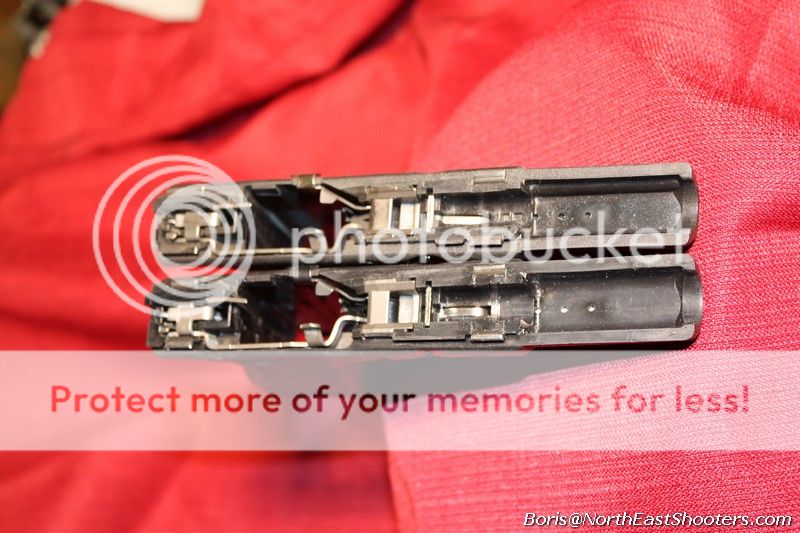
the slide goes onto rails (g17 and 22 shown)

p89.jpg

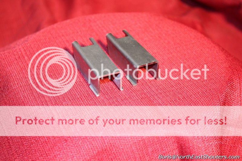
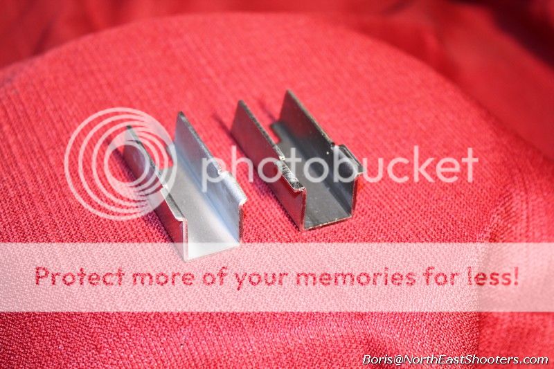
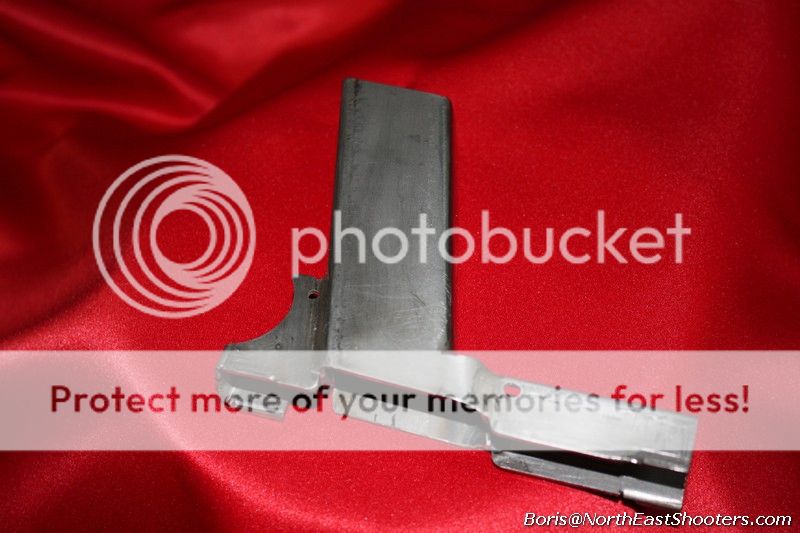
You need to grind the fore-piece to replicate this experience for your slide. Here is the fore-piece that comes from a kit (right) and completed (rails ground, left)

p90.jpg


p91.jpg

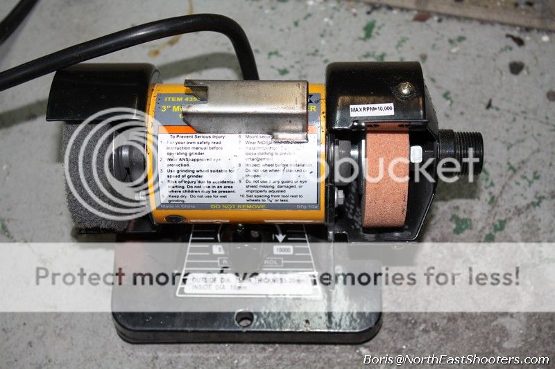
The piece from the kit has rails that are too big to "readily" fit into the slide, among other things. To grind those rails I like to use small grinder simply because it takes off very little material at a time. Since no one was ever been able to cut shit any longer, you got one shot at grinding the rails right.

p59.jpg

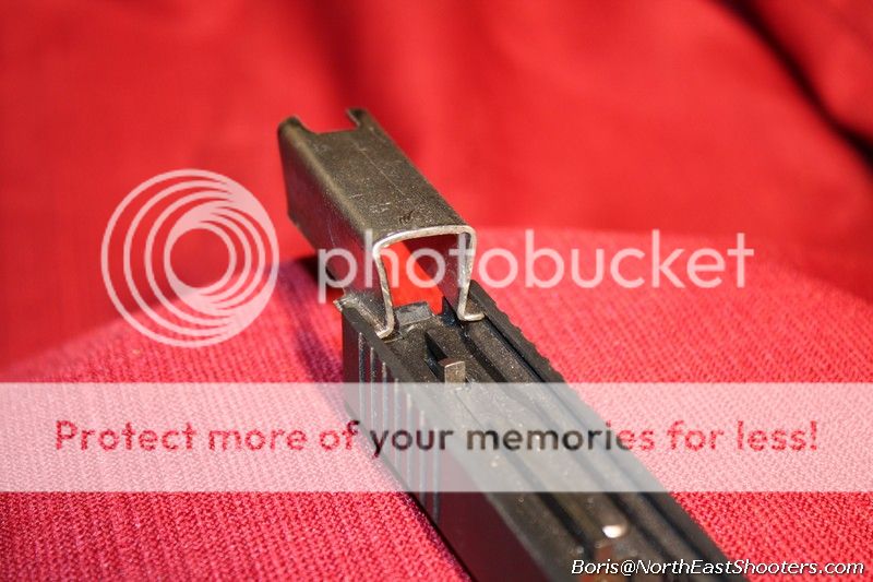
Go slow and check the rails against the slide often. Keep in mind that rails are slightly thicker than they should be. Work on width first.

Don't try to jam the fore-piece into the slide by bending the top ends. It should slide in easy yet not fall out. When you think that you got the width right, use small hand file to adjust thickness. You should always file the rails from under, never from the top, since the top surface of the fore-piece should be flat and even across the entire piece.


[table="vertical-align:bottom"]
[tr]
[td]
dontdoit.gif~original
[/td]
[td]
p92.jpg
[/td]
[/tr]
[/table]

When rails are ground correctly, you can slide them all the way forward. Mission completed!

p93.jpg

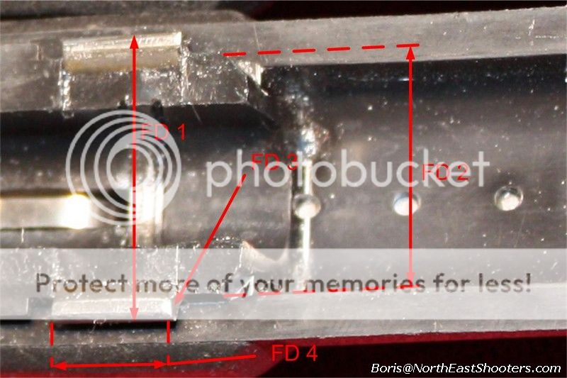
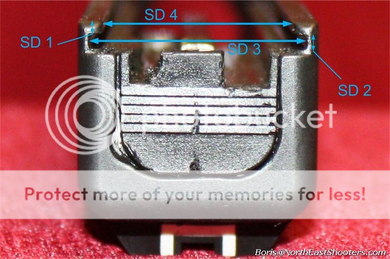
Here are some dimensions that you may find useful. Keep in mind that there is some variation in slides, especially aftermarket slides.

[table="class: outer_border, align: center"]
[tr]
[th]Dimension[/th]
[th]Description[/th]
[th]Austrian millimeters[/th]
[/tr]

[tr]
[td]FD 1[/td]
[td]Frame rail width[/td]
[td]22.89-22.91[/td]
[/tr]
[tr]
[td]FD 2[/td]
[td]Frame inside rail width[/td]
[td]19.19-19.33[/td]
[/tr]
[tr]
[td]FD 3[/td]
[td]Frame rail thickness[/td]
[td]1.2 - 1.4[/td]
[/tr]
[tr]
[td]FD 4[/td]
[td]Frame rail length[/td]
[td]10.1 - 10.2[/td]
[/tr]
[/table]


p94.jpg


[table="class: outer_border, align: center"]
[tr]
[th]Dimension[/th]
[th]Description[/th]
[th]Austrian millimeters[/th]
[/tr]
[tr]
[td]SD 1[/td]
[td]Slide groove outer width[/td]
[td] ~1.2[/td]
[/tr]
[tr]
[td]SD 2[/td]
[td]Slide groove [/td]
[td]between 1.58 (go) and 1.63 (nogo)[/td]
[/tr]
[tr]
[td]SD 3[/td]
[td]Slide major width[/td]
[td]~22.7[/td]
[/tr]
[tr]
[td]SD 4[/td]
[td]Slide minor width[/td]
[td]~20.05[/td]
[/tr]
[/table]


p95.jpg

Step F2
Fit the locking block

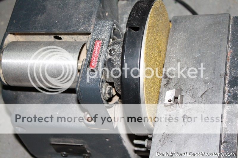
The only part from LPK that you need to permanently modify is the locking block. You need to make it 1mm narrower, just enough to fit in the fore-piece. You need to take about 0.5 mm on each side, making sure that you do it uniformly. A grinding wheel has some curviature and is usually too coarse. I use belt sender to do this. It works well. Check you fit often. Make sure that you don't try to force the block into the fore-piece, spreading it apart. It's sized just right to go inside your typical slide, so spreading it will not allow slide to move freely.

p02.jpg

Also, the bottom of the fore-piece is not perfectly square but somewhat curvy. The locking block must sit flush, right on the bottom. Thus, you may need to make the end of the fore-piece square by using square hand file or round the bottom of the locking block ever so slightly.

p03.jpg


Step F3

Drill the hole in the locking block.
Locking block is being held in the frame with a pin that goes into the hole. There should be at least one hole. But it's like during that Thai vacation, if you find the second one, you are better off.

Drilling the hole must be done really precisely which you'll never be able to do. So when you are marking, err on the side of pull - i.e. toward lower midsection. That way you can widen or expand the hole later, with pin still pulling the block down to the frame.

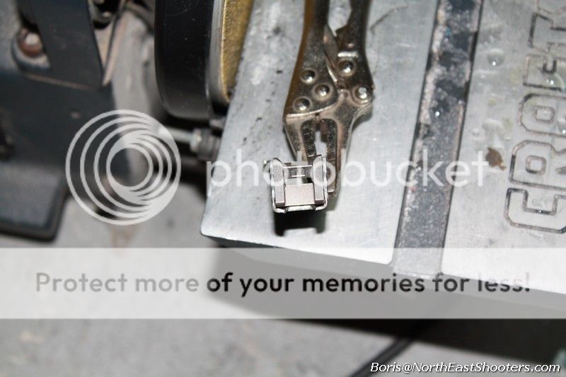
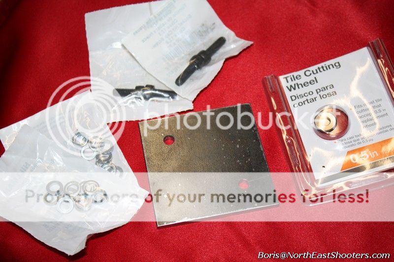
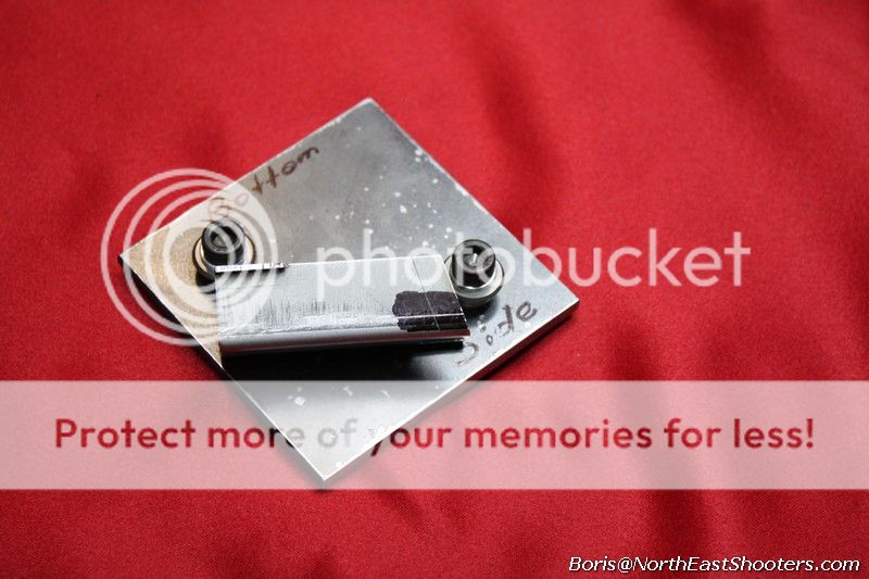
Here is a jig to accomplish marking of the hole. I start with some carbide tile blades (usually come in 2) and some M6 bolts to fit the hole, some M6 washers, plus a 3"x3" plate to mount these on.

p83.jpg~original

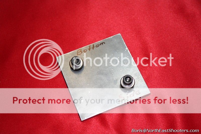
Putting jig together is pretty easy, use some washers as spacers between the carbide blade and the steel plate. To increase distance add washer, to decrease distance, hammer one of the washers with a hammer. Do it until you get the distance perfect.

Here is the jig assembled:

p84.jpg~original

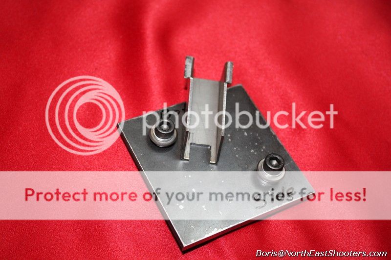
This is how you mark the fore-piece, by darkening the spot with a black marker, than dragging it over the blade.

p85.jpg~original

What you end up with is perfectly marked sides:

p86.jpg~original


The only other question is how to determine what distance you need to set the marks at? Use micrometer, measure the thickness of the metal, should be about 1.44mm, then add the distance to the center of the hole. Set that distance and see how well the jig marks the distance by marking a piece of scrap. You need to err slightly toward either edge.

Step A1
Smooth all the edges
Grind rails similar to how you did the fore-piece.

p100.jpg~original


p101.jpg~original


Step A2
Fit adjacent sides, trigger mechanism housing.

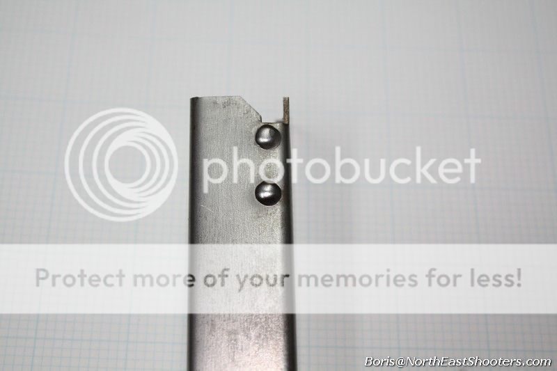
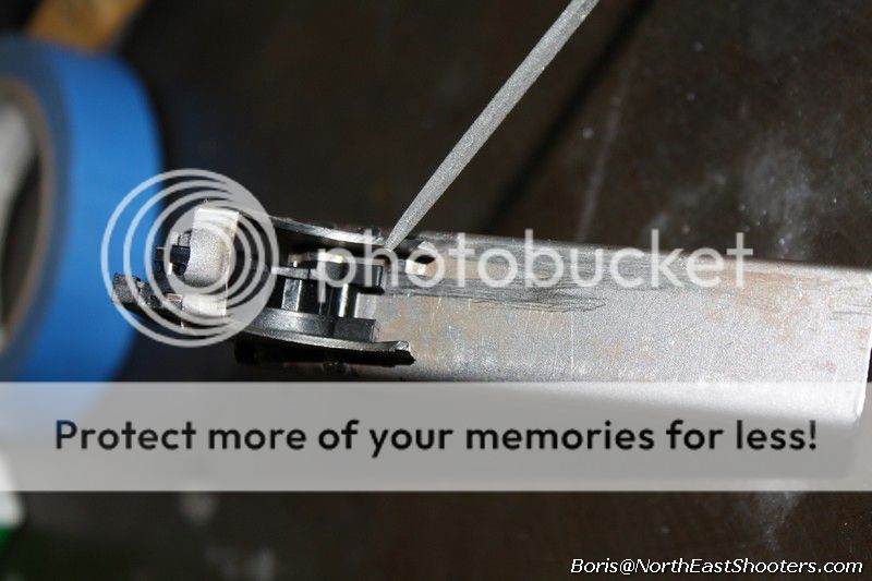
The aft-piece will hold the trigger mechanism housing, keeping it to the left. You will be welding it to the midsection, so make sure that the housing is just the right size. Your piece from the kit will be slightly over-sized and you will need to file it down to just the right size on both edges. When you tack it to the mid-piece, the weld joints will pull it tight and the housing should not be loose.

p102.jpg


p103.jpg


p104.jpg


Step A3

Drill a hole in the aft-piece

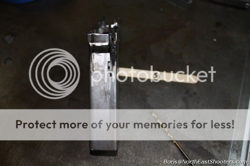
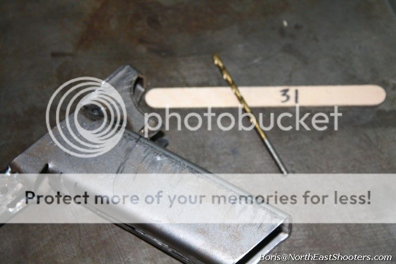
From step 2, you should see how the trigger mechanism housing suppose to fit in the aft piece. What's remaining is to drill a hole to hold it in place. Support the sides with a bunch of popsicle sticks to keep sides from squishing.

p105.jpg


The drill bit that you need is #31
 
Last edited:
Step M1

Smooth all the edges of the mid-piece.


Step M2

Weld grip gap
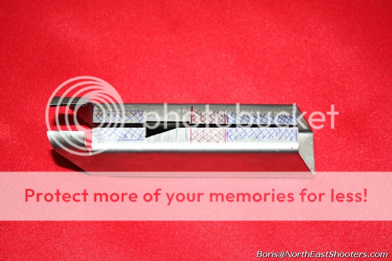
The mid-section is bent, but you will need to join it by welding in three places, at least. Red is where you must weld. This is where the spring will sit that will tension the mag catch. If you will be finishing with an airsoft frame, this is not necessary. Blue is where you can weld if you like. Don't weld over that triangular gap, that's where the spring will go.

p80.jpg~original

Keep the top rails parallel:

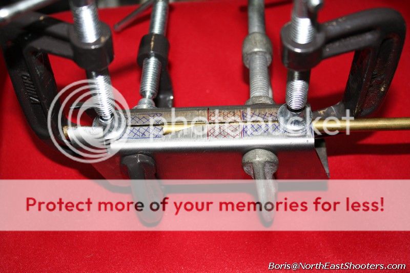
p69.jpg

Use aluminum or brass 1/4 inch rod as backing for the weld joints. You will have to leave some space at the joining sides, so use a nail to keep that spacing. Remember, when the hot metal cools it will pull both sides together, making the mag well smaller, hence you really need the spacers. Also, before welding, use a mag to make sure that mid-section is not too tight.

p79.jpg~original

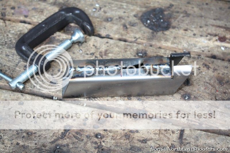
here it is welded

p77.jpg~original

weld joints ground

p76.jpg~original

... and sanded

p75.jpg~original


Step M3

Grind dimple for the aft piece
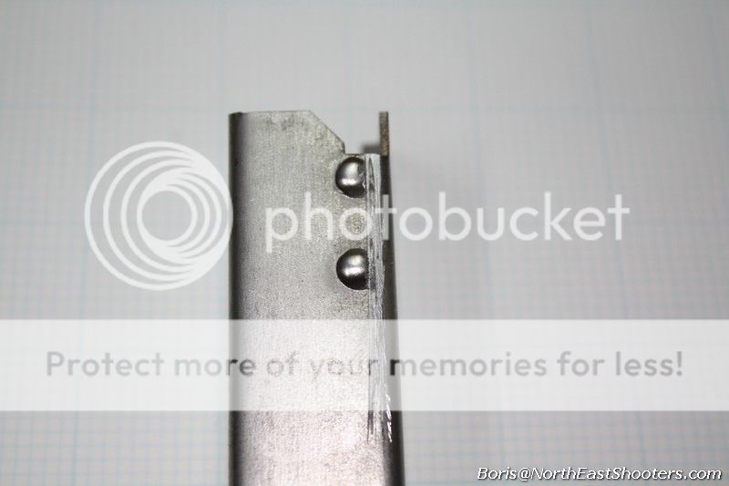
There are two dimples on the back of the mid-piece. Their purpose is twofold: keep the trigger mechanism housing in position and to hold aft-piece at the right place when you will be welding it to the mid-piece later.

p63.jpg

Start cutting the dimples flush with the back surface of the mid-piece with a sharp square hand file. You will get to something like this:

p64.jpg

When you are done, the aft piece will sit perfectly in the middle of the midsection.

p65.jpg


Step J1

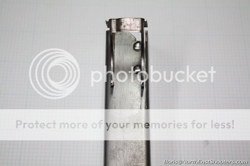
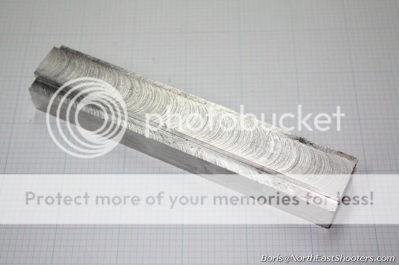
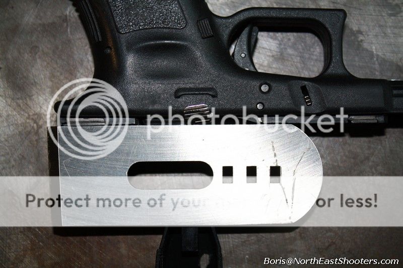
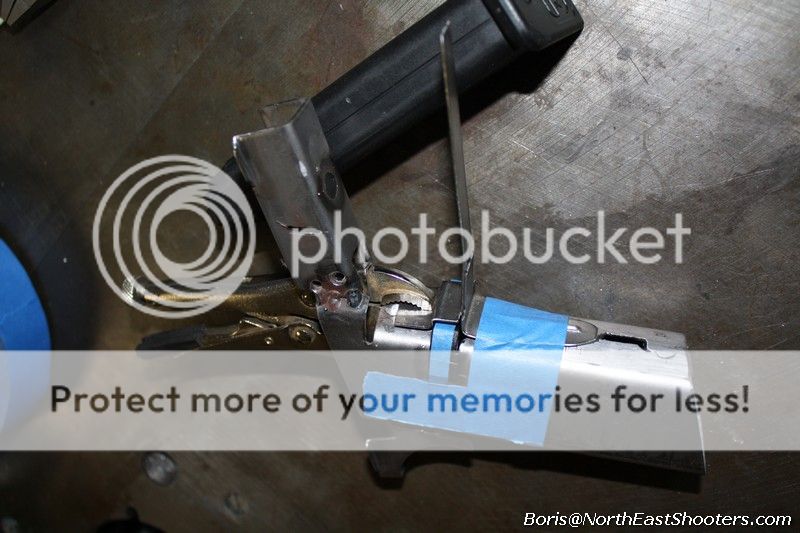
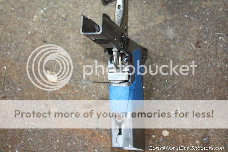
Join aft, mid and fore-pieces together. There are few ways to accomplish this. Although this can be done "on a slide" I do not recommend it, as it usually turns out badly you will get rails that don't line up. I use a piece of aluminum to setup the three pieces in position:

p66.jpg

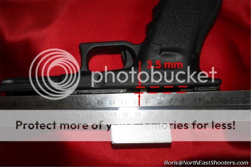
This piece of aluminum is pretty easy to make. The width of the top end is 16.25mm or just wide enough to have for and aft pieces to fit on it snugly. It is used to line up rails. The height of the step down is about 3.5 mm or the distance between the top rails and grip. Other dimensions are not vital.

p99.jpg


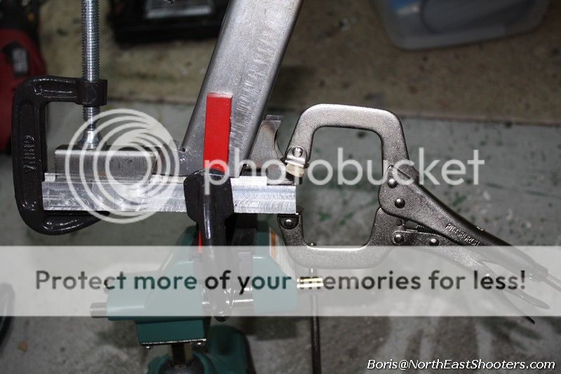
I attach clamps like this and check that all pieces mate well together like a happy troop of monkeys. There should not be gaps where adjacent metal pieces come together. The pieces have to be straight.

p67.jpg

Tack weld them together. Check that rails in front and in the back are perfectly parallel. If not, cut the joint with dremel and smoke it. Then tack weld again.


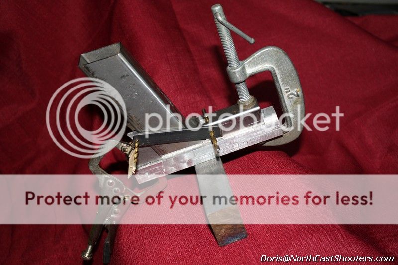
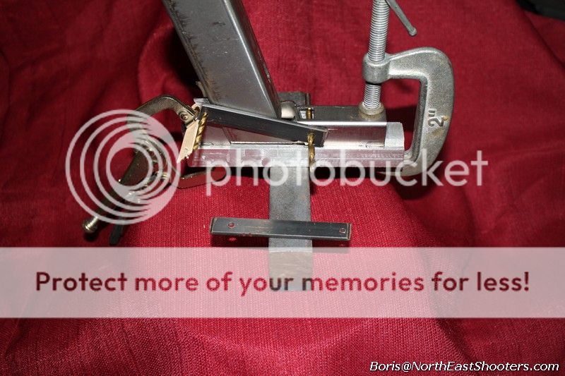
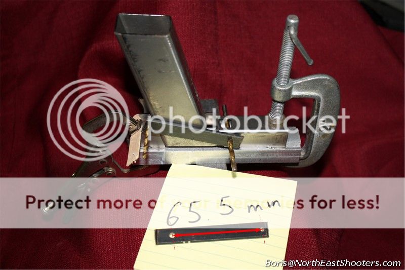
Here is another build, I am setting up all three pieces and checking the distance between the holes on fore and aft piece.

p106.jpg~original


p107.jpg~original

The "template" that I am checking against is just a piece of 1/2 steel with two holes (#22 and #31) drilled with 65.5 mm between centers. This is a good idea to do because this will help the trigger-bar-housing to work smoothly. I have screwed up this dimension before, it's not as critical as some clearance spaces but it's a good idea to have it right.

p119.jpg~original


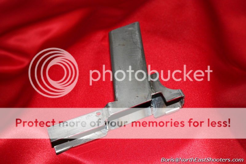
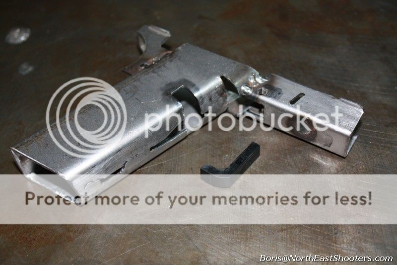
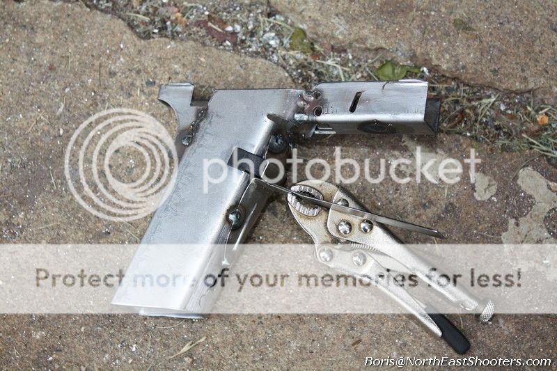
after welding three pieces together and cleaning up the weld-joints, you should see something like this:

p108.jpg~original


p109.jpg~original


p110.jpg~original


Step J2

Grind dimple for the trigger mechanism housing
This step could be done after all sections are joined together. The two rear dimples act as spacers, and they help to hold the trigger mechanism housing in place. Use square hand file to make a nice, 90 degrees cut to reduce the dimple size until the trigger mechanism housing can be inserted for a snug fit.

p30.jpg

Once the trigger mechanism housing is all the way in, you need to mark and drill the holes for the pin that holds it in place. Use #31 drill bit to do it. Use any method to make it so the housing is getting slightly pulled down.

p29.jpg


p31.jpg

At this point you can assemble and join your trigger bar with the trigger mechanism housing. There are more than a few vids floating around on how to do it. No special tools are required.

p32.jpg


p33.jpg


Step J3

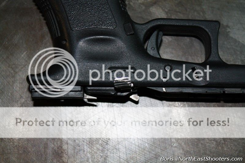
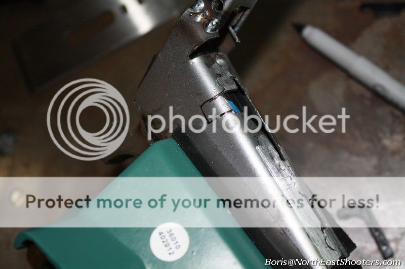
Cut notch for slide stop lever. That's a 2 min job. Just put the slide stop lever in, mark and file vigorously ... or not, until you got the notch.


Step J4

Fit and weld spring stop. This is the insert that holds the slide spring.

p111.jpg~original


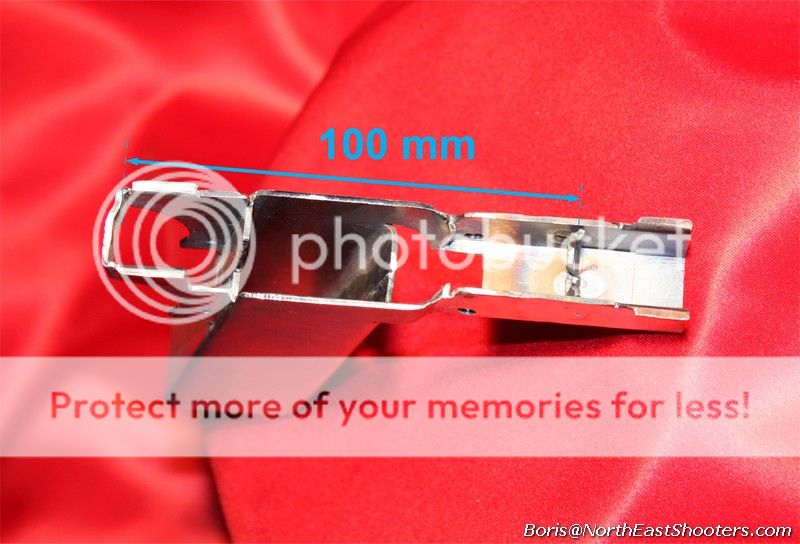
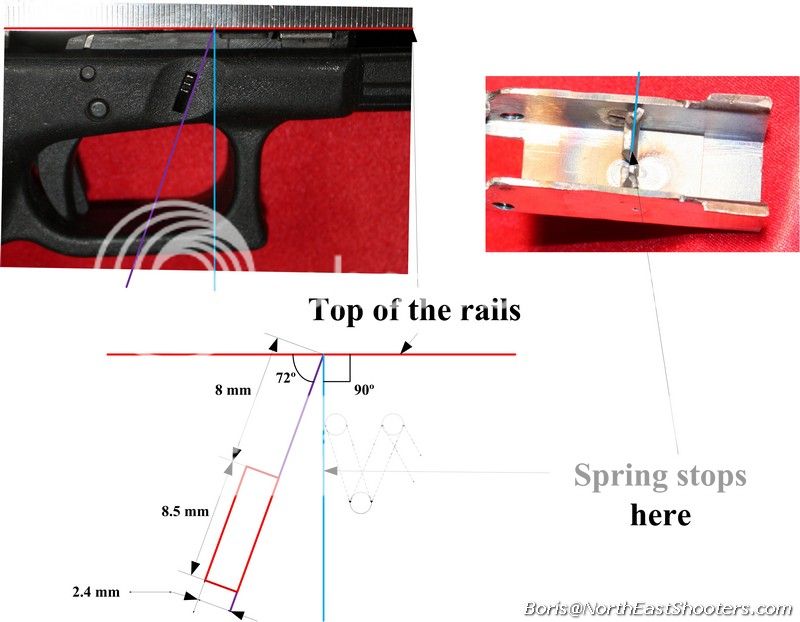
It's critical that it's positioned in the right place. Since spring returns the slide, if this piece is too far forward, spring will be under too much tension when pistol is ready to fire. If this piece is too far back, spring will not have enough tension to return the slide into position when loaded and you will not be able to fire the pistol.

This is how I measure the distance:

p96.jpg~original


This Back to Front Stop distance is different for 17-19-26 kits

[table="width: 500"]
[tr]
[td]Kit[/td]
[td]Distance (mm)[/td]
[/tr]
[tr]
[td]Merigold 17-22-31[/td]
[td]100[/td]
[/tr]
[tr]
[td]Snapdragon 19-23-32[/td]
[td]95[/td]
[/tr]
[tr]
[td]Daisy 26-27-33[/td]
[td]93[/td]
[/tr]
[/table]


Take note which points I am using as references:

p97.jpg~original


p98.jpg~original


To secure this insert, make sure that it fits snugly in, it is typically a tiny bit oversized. Then drill 3 1/4 or smaller holes in the fore-piece.

p112.jpg~original

clamp it

p113.jpg~original

weld sides, then take off the clamp and weld the bottom. You just need to fill the holes while grabbing the piece on the inside.

p114.jpg~original


p115.jpg~original


p116.jpg~original


you may then grind and clean up the weld points

p117.jpg~original


p118.jpg~original


Step J5

Cut opening for the slide stop.
The slide stop opening is a rectangular opening and you may look into an actual glock to get dimensions right.

WARNING: This is G17-22 (Marigold) example. For G19-23 and G26-27 it's different. Look at the guides here:


Marigold G 17-22 guide

Snapdragon G 19-23 guide

Daisy G 26-27 guide


p118-1.jpg~original


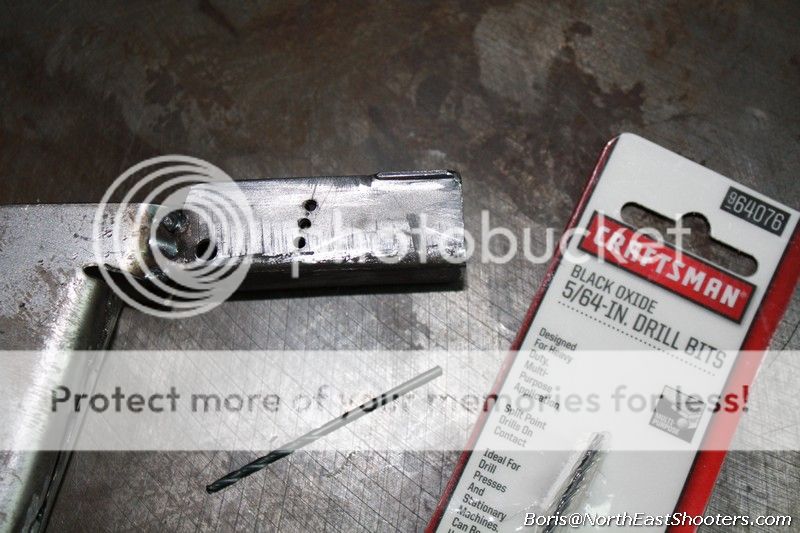
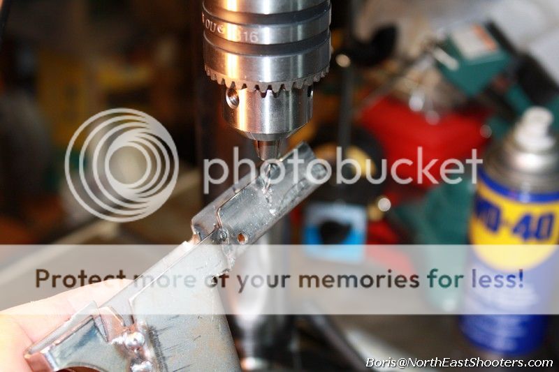
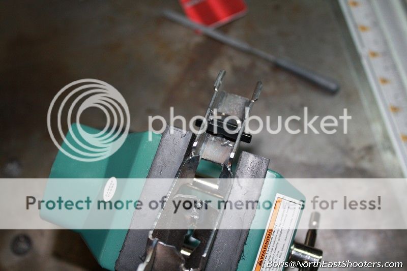
Initially this looks like a painful task to cut the square opening, but in reality it's quite easy. Once you know where the slot suppose to me, dril a few holes with 5/64 bit.

p04.jpg

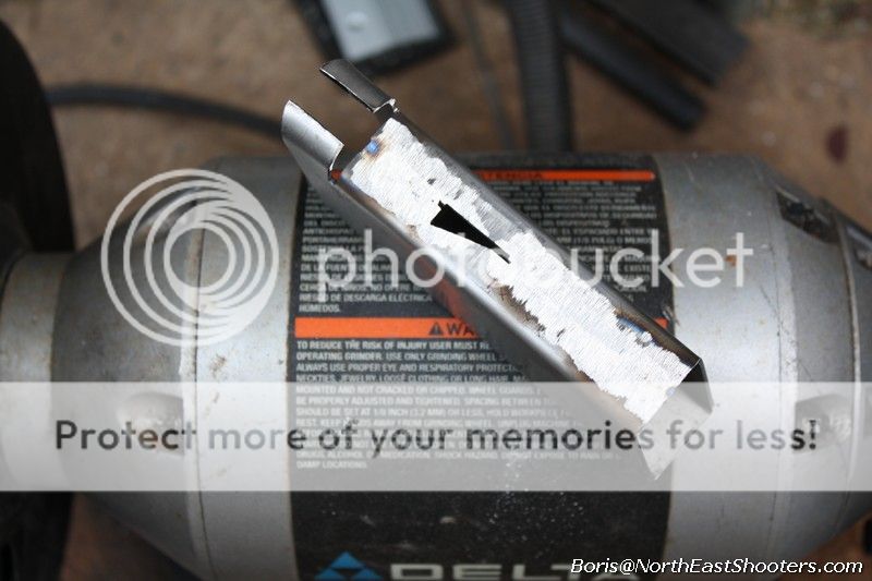
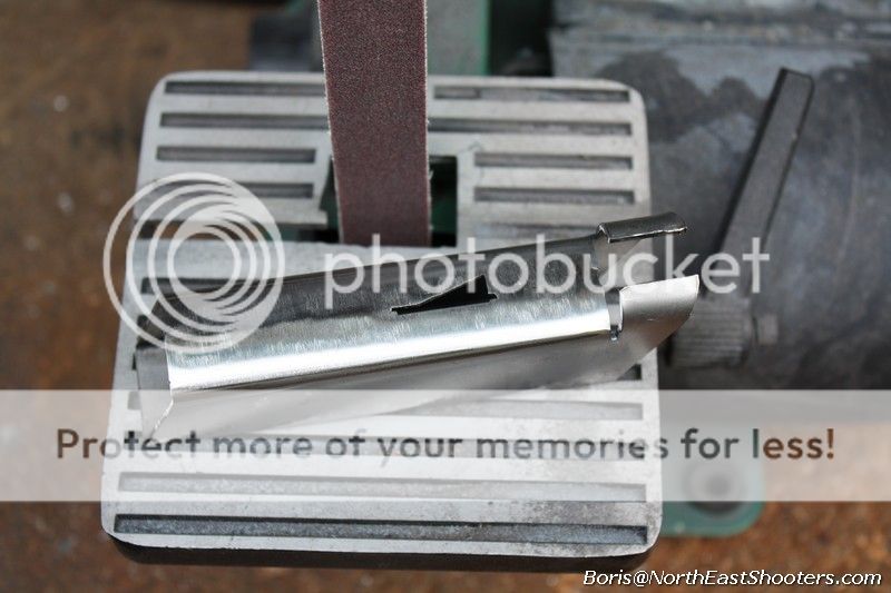
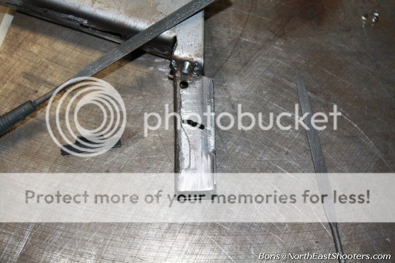
what you want to do next is using the same bit on a low speed, pivot the fore-piece and use the drill bit as a mill to cut the space between the holes. The bit is pretty fragile, so go slow. With experience, you will know how far you can push the bit before it breaks. What you will end up with is quite reasonable opening.

p05.jpg


p06.jpg


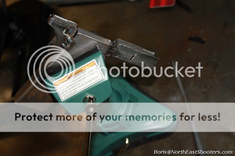
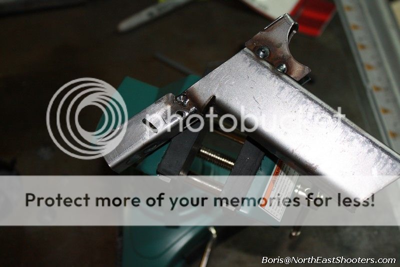
I use a small, pivoting vise to hold the work piece while inserting a hand file, making in-out movents.
p07.jpg

p09.jpg

Here is the slide stop lever inserted into the completed hole.
p08.jpg

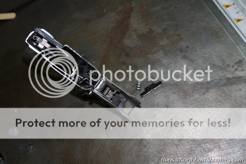
There are a couple of ways to hold the slide stop together. One is to use Glock's original leaf spring. This is possible if you will be finishing up your pistol with a trigger guard that's not bare metal. Otherwise, you may use a small section of a coil spring.
p34.jpg

Keep in mind that if you intend to use a gen 4 slide, Glock's original leaf spring may interfere with wider spring of g4 slide. In plastic frame (like in a condom) it's tucked away from interfering.
 
Last edited:
Step J6

Cut slot for magazine catch
This step is not cruicial if you are finishing up with airsoft frame. Otherwise you need to be precise.

To answer the question about the mag slot location. It will be slightly different on each frame, depending on how you weld three pieces together. This is why it's not cut out for you in the kit piece. The position of the middle piece is less crucial in relation to the top of the rails. It can vary. The slot for mag catch needs to be precise, but only after all three pieces are joined together. Building this way gives you latitude how you assemble three pieces (mid, aft and fore) without worry if mid piece is perfectly located.


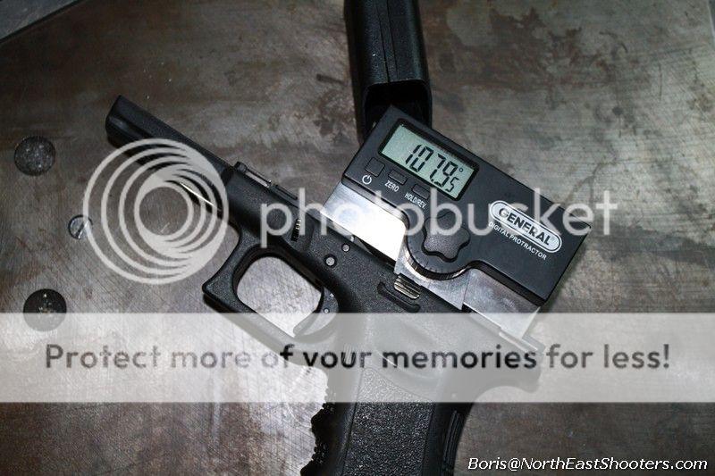
For this step you will need actual magazine (you'll need it sometime anyway) and another Glock, but not necessarily. Insert mag into a pistol and note/mark how it stays in relation to the top rail.

p10.jpg

Use something with a straight edge as your guide.

p11.jpg

You may also use an adjustable angle to get precise angle too.

p12.jpg

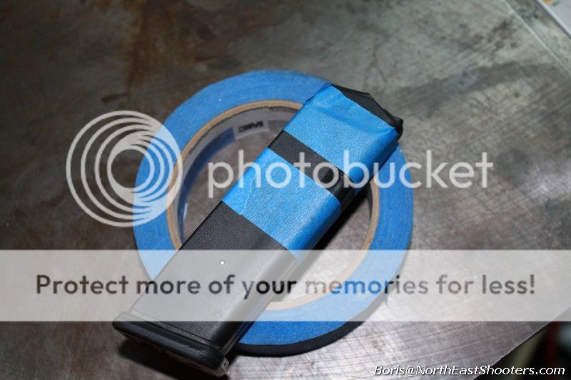
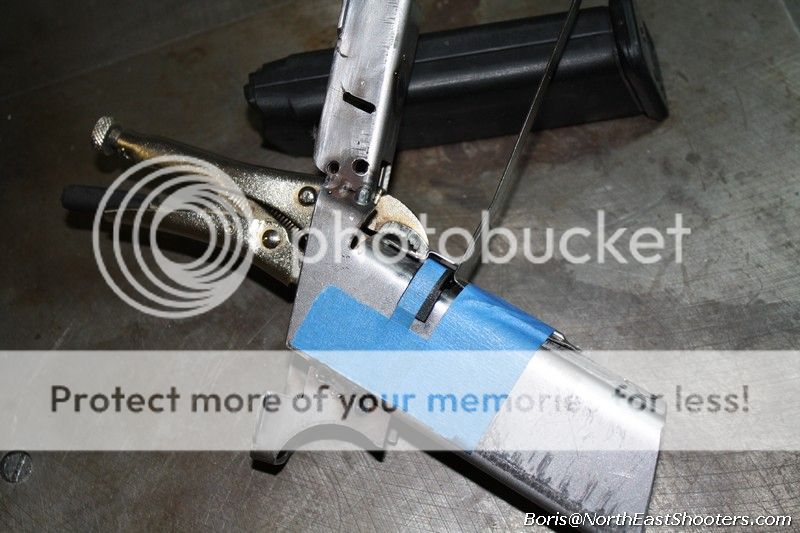
Mark the mag with painters tape indicating where the notch is.

p14.jpg

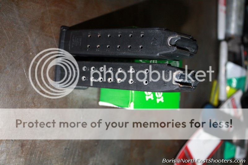
Also keep in mind that Glock mags for 9mm and .40 are slightly different in length, i.e. the distance between the bottom edge and the notch is about 3 mm shorter on G22.

p15.jpg


p16.jpg

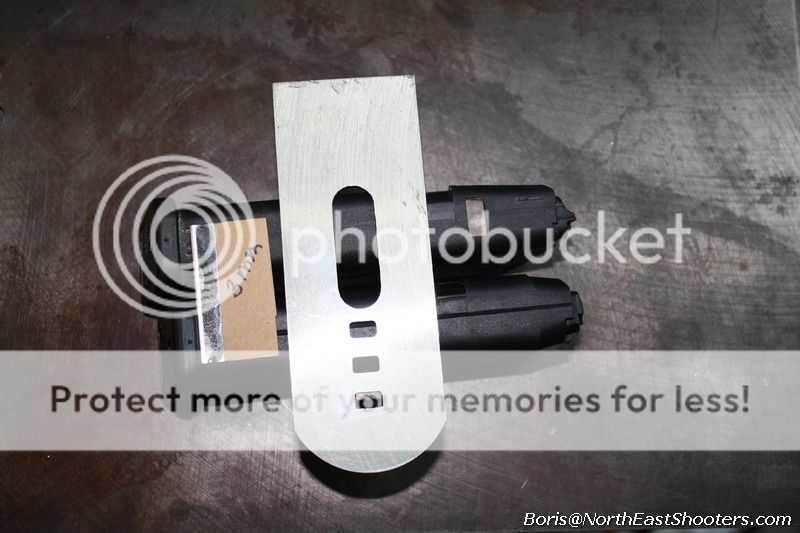
Marigold-1 kit comes with the mid-piece that would work flush with 9mm mag. If you want to use .40 mags, you need to cut it about 3mm shorter.

At this point you want to note how much space you got in-between the mag and the arch of the grip.

p17.jpg

It would be slightly different between grips and however you will be cutting the slot for the mag catch (dremel or mill) you don't want to go too deep.

p18.jpg

When you rest something straight on the opening, it should not touch the mag, but be very close to it. If the cut across is too deep, your mag catch will cock-block magazine from sliding into the mag well.

p19.jpg

The rest of this is not rocket science, mark around the mag catch and cut the rest on the left side.

p20.jpg


p21.jpg

Here it is completely cut out, edges are smoothed and polished.

p22.jpg

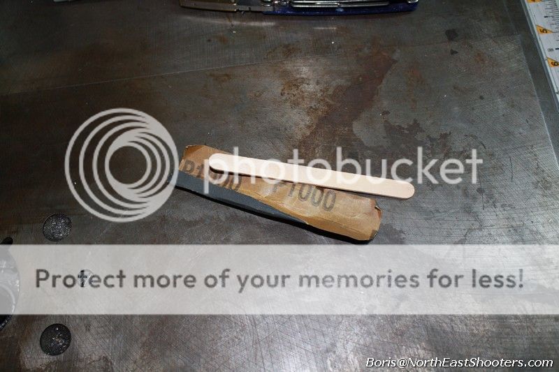
To polish edges and what not, you can use a popsicle stick wrapped in whatever grade of sandpaper that you need.

p24.jpg

For the magwell, I use a stick close to the dimensions of the mag with wrapped sandpaper to size and polish the magwell.


Step J7

Weld top trigger guard pieces

If you want to have a steel trigger guard (not needed if using airsoft body) you need to fit and weld the last two pieces. I am using bits of masking tape to hold magazine catch in place while I line up the upper and lower sections of the trigger guard.

p25.jpg

The place where mid section is joined is not flat, so laying out flat pieces on it is somewhat a challenge.

p26.jpg

Pull the plastic magazine catch (you don't want to melt it) and tack both pieces in place.

p27.jpg

When metal is cool, align the top and lower section of the trigger guard and tack them together.

p28.jpg

to finish, use channel lock pliers to bend both top and bottom pieces around the mid-piece. At this point they all should be tacked together. Then do few more tacks and grind off excess of material.

p47.jpg


Finishing up

There are several ways to finish your pistol. You can leave it as is and let it rust naturally. You can blue the metal.

p68.jpg

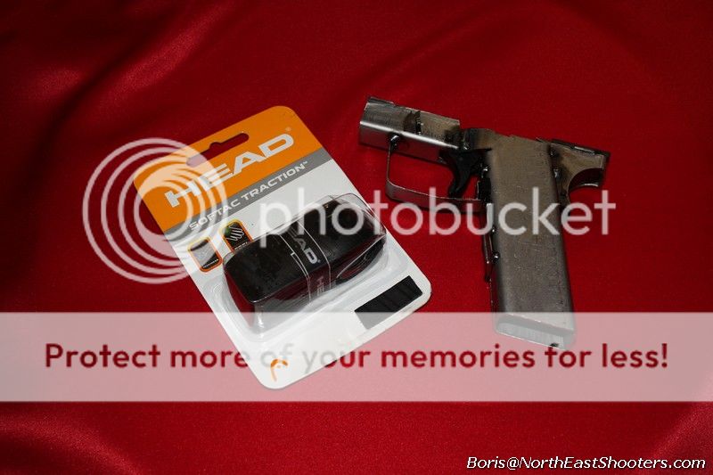
You can paint it or just get some head. It's never a bad idea to get a head.

p56.jpg


p57.jpg

For the AR people, you can improve your accuracy and your confidence around your mom's basement by adding tactical unicorns with horns ribbed for his pleasure and fruity shit.

Look at that mother****ing unicorn! It got rainbow coming out of its ass!

p58.jpg

Alternatively you may shape it's body out of fiberglass, melted plastic (see plastic welding) or use two parts bumper repair epoxies.


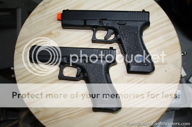
You may use an airsoft body. Here is a real Glock and an airsoft G17 by HFC. The airsoft pistol is spring powered and could be found for less than $20. It's actually wider than the real thing, much closer to the dimensions of G21 than G17/22.

p35.jpg

There is a "Made in Taiwan" markings that would puzzle Glock collectors as the "rare Chinese contract gun" ; )

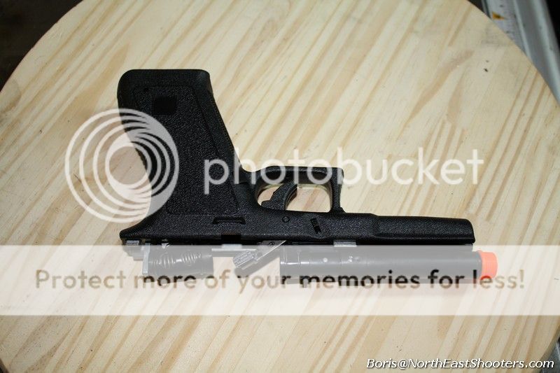
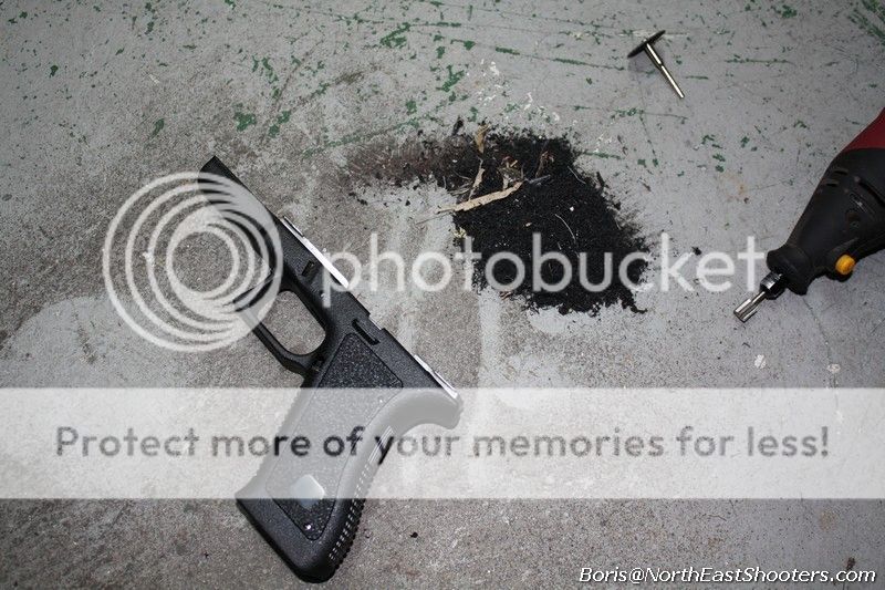
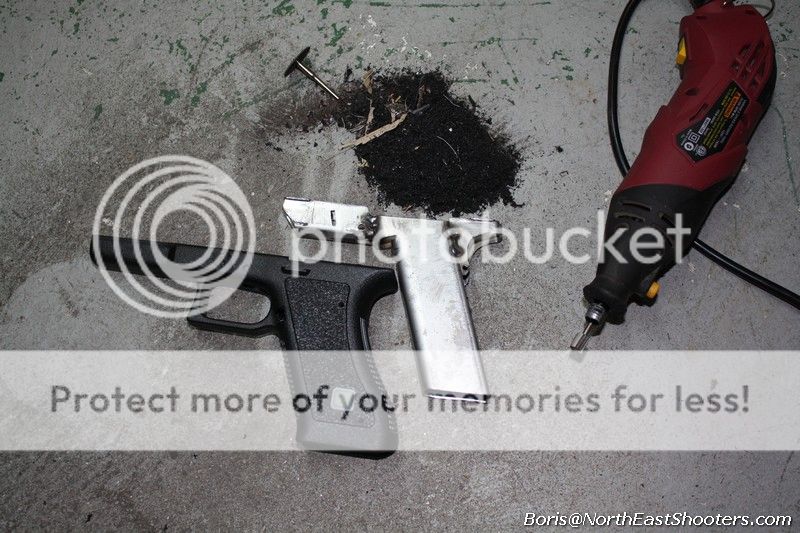
You can rip the airsoft pistol with your bare hands and remove all the fruity crap.

p36.jpg

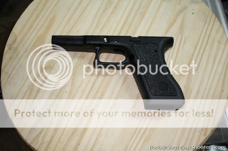
what you are left with is nice, bottom piece.

p37.jpg

The inside is almost perfect fit

p38.jpg


With some dremel work it is ready to be cool.

p39.jpg

Your iron frame will fit right in. I did not even glued mine.

p40.jpg

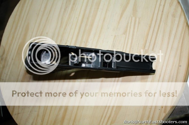
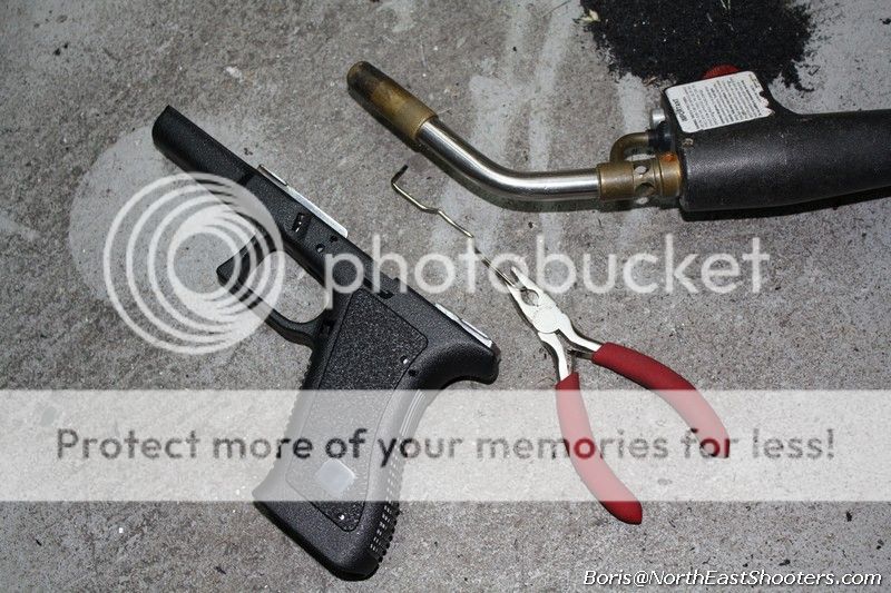
To make the holes in plastic, put the iron frame in and use a paperclip heated with a torch to reach inside and pierce the plastic where holes for the retaining pins should be.

p41.jpg

If you are building fotey version, your grip length may need to be reduced.

p42.jpg

Mag catch is a little more complicated. The notch on the airsoft pistol is just slightly, 2-3 mm below where it should be. That is, you need to build up some material to bring it "higher".

p43.jpg

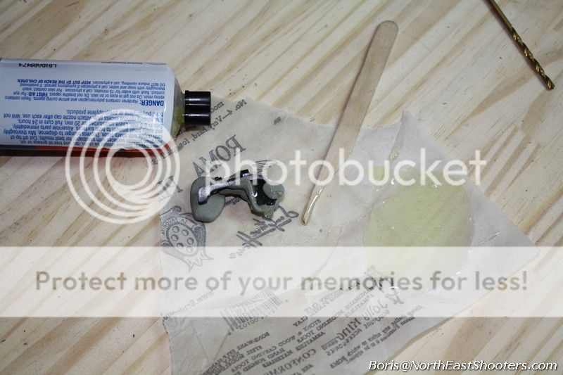
I did this my using two part epoxy and using modeling clay to contain liquid epoxy from going everywhere it should not go.

p44.jpg

Mag catch on airsoft pistol, this maker at least, is different from how Glocks put together their catches. I used airsoft catch. Putting it back in is tough to describe, it's painful but there is only one way to do it.

p48.jpg


Mech-Tech


For those who crave rifles, there is an option of Mech-Tech (MechTech - Home) For mere $360 you can have an entire upper that goes with your Glock lower instead of the slide.

glock_full_full.jpg

here is how it looks with all the damned rails you can put on it and an actual Glock lower:

mt01.jpg~original

Question, would it work with Iron Glock? Well, WyTF not?

mt02.jpg~original


mt03.jpg~original


mt04.jpg~original

scroll down to the movies section to see how it shoots.
 
Last edited:
Common Issues and Problems


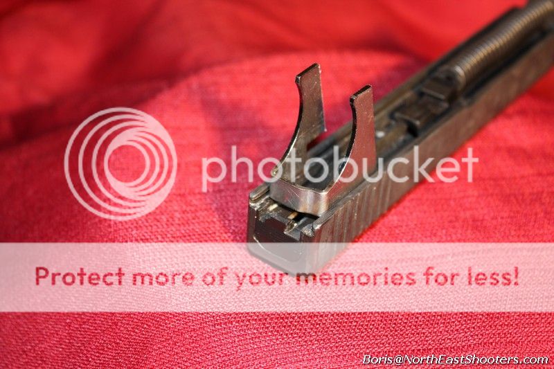
When you Glock is assembled, check that trigger bar has adequate space to go up and down. Frequently, if there is not enough room, it may not go down enough to release the stricker. In an assembled kit, you will not hear a clicking sound of releasing the trigger once you pull the trigger.
The solution is to grind the bottom of the surface of the aft piece so there is room for the trigger bar to move.

p00.jpg


Wunderbar! I know, I know Austria is not even a real country, it's like a German Canada.

p46.jpg


))<>((

and a special thanks to my homie Mike from saiga-ak.com, without him I'd be building an Uzi and ShadyDuck in filming this trainwreck.​


... and talking of movies ...


trying out the airsoft frame


doing same outside


running naked iron glock ... for the motherland!


making sure it works for homies


... and for australians


Shooting with Mech-Tech upper. Notice that this is a new Mech-Tech unit with under 50 rounds through it. The ejection is pretty anemic. Perhaps the tube will "break in" for better ejection later, who knows. Just to make sure that it's not my lower that's giving the trouble, I shot a few rounds with just a regular 9mm slide to compare ejection.

[video=youtube_share;MYtoCa2cKY4]http://youtu.be/MYtoCa2cKY4[/video]

[video=youtube_share;uowf8bmT_NY]http://youtu.be/uowf8bmT_NY[/video]

[video=youtube_share;R11GIUc1cNY]http://youtu.be/R11GIUc1cNY[/video]

[video=youtube_share;8kOS5JwKvJs]http://youtu.be/8kOS5JwKvJs[/video]

[video=youtube_share;tTTUReIn2ak]http://youtu.be/tTTUReIn2ak[/video]​
 
Last edited by a moderator:
I wanted to mention this since the first time I heard about it at last year's Christmas party. Amidst the distractions of beer and boobs I admit I was skeptical but had faith.

Well done Comrade!
 
It looks really neat, but $200 seems rather excessive for the Marigold-1 kit, especially when you consider that can buy a real Glock fame in a free state.
 
As a lot of you know, i am a 1911 guy. I want very badly to like glocks because they are so simple, like my beloved AKs, but i hate how they point as compared to a 1911. When you draw and aim with one of these, even in the airsoft frame, it points without making you feel the muzzle is pointing at the sky. Also the bare frame is not bad at all to shoot. Its actually comfortable.
 
It looks really neat, but $200 seems rather excessive for the Marigold-1 kit, especially when you consider that can buy a real Glock fame in a free state.

it's for people who don't live in free states and for people who enjoy building things with their own hands.
you can buy an AK for $600 (or even less if needs be) in the free state but even in those states people buy $600 worth of jigs and various other building equipment so they can make their own AK from scratch.

this is hardly about economy aspect of the issue. you CAN buy new glock for normal price ($550) in MA if you are willing to do legwork and search patiently. but does it stop people from buying glocks for retarded MA prices like from $750, $850 to even 900 bucks?

this build is also about being free and doing free-man shit even if you stuck behind Iron Curtain of Assachusets.
 
Last edited:
Back
Top Bottom