• If you enjoy the forum please consider supporting it by signing up for a NES Membership  The benefits pay for the membership many times over.

DIY: LED Light for your Progressive Reloading Press

beaker

NES Member
Joined
Jun 30, 2009
Messages
13,323
Likes
14,902
Location
LV-426
Feedback: 26 / 0 / 0
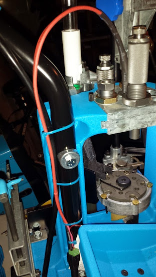
I made this for a Dillon xl650 press, but it should work in any progressive reloading press, you might have to make some mods. Progressive presses are great, but they have a large turret or tool head which blocks all available light like a black hole - which makes it difficult to see what is going on inside. I like making stuff, and didn't want to spend $35-40 on a light so I found a suitable bulb and went from there.

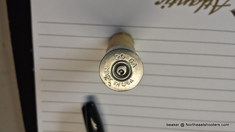
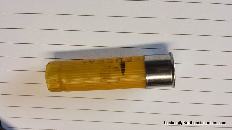
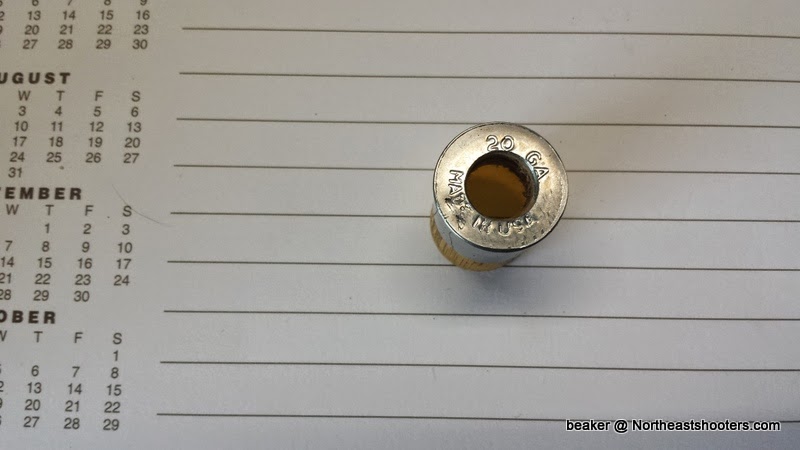
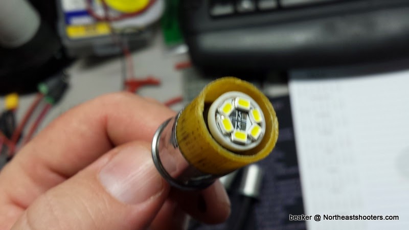
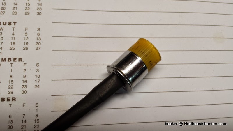
SEE POST #10 ON A BETTER WAY TO MAKE THE BODY OF THE LIGHT USING A 20G Shotgun Shell casing! A LOT EASIER AND FREE!

n9WPt1gyD2fuqRjCYKUhKMsaGZl5AzxGJFtprBRAZPk=w311-h553-no


Light+for+Dillon+1-001.jpg


Light+for+Dillon+5-001.jpg


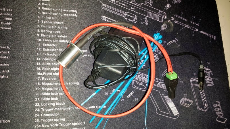
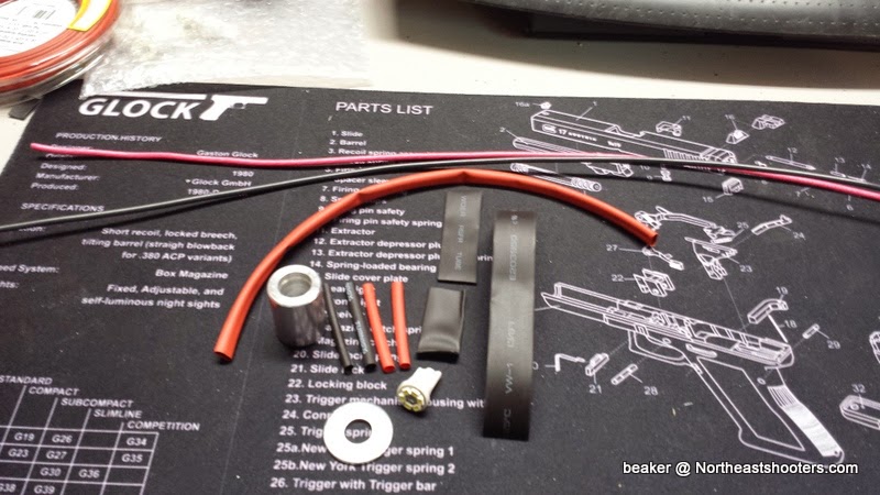
The bulbs are pretty cheap, and I had many of the components and tools needed to make the light, you can adapt the idea and basic concept. I bought the bulbs and connectors on eBay. I had the shrink tubing already, most of it from Harbor Freight.

So here are the materials and tools you need to do this.

Tools

Soldering Iron
Heat Gun
Hot Glue Gun and Sticks
Misc hand Tools - wire cutter, wire stripper, razor knife, screwdrivers, scissors etc.
Hand Drill (or a drill press)
Vice
Step Drill bit with 15/32 and 3/8"
1/2" Drill Bit

Materials

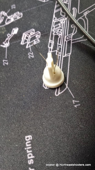
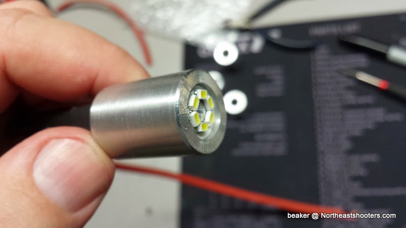
LED Bulb - I got this one that came with 10
( http://www.ebay.com/itm/111403644190?ssPageName=STRK:MEWNX:IT&_trksid=p3984.m1439.l2649 )

These are the same but 4 of them
( http://www.ebay.com/itm/261512253147?ssPageName=STRK:MEWNX:IT&_trksid=p3984.m1439.l2649 )

DC Power Connectors (5.1mm Female) You could use other means as well (different connectors, solder the wires together, etc.)
(http://www.ebay.com/itm/221450501242?ssPageName=STRK:MEWNX:IT&_trksid=p3984.m1439.l2649 )

Aluminum Spacer (0.750" x 1")
( http://www.mcmaster.com/#92510a360/=swv6p0 )
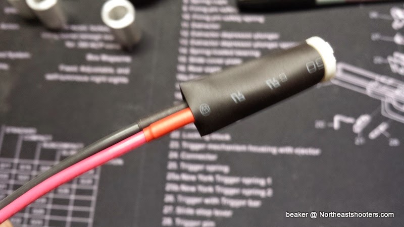
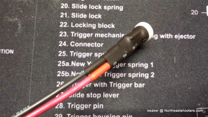
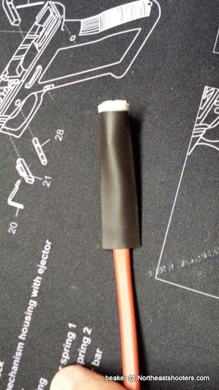
Shrink Tubing
3/8" - Harbor Freight - Black
1 @ 1.25"
1 @ 2"
1 @ 5"


11/64" - Harbor Freight - Red
3mm - I had this, need to procure some around the same size RED and BLACK
1@15"

Wire
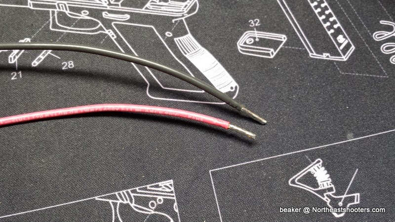
14 Gauge Stranded - RED and BLACK - DON'T USE SOLID WIRE. 16 Gauge would work fine as well, nothing bigger than 14 though.
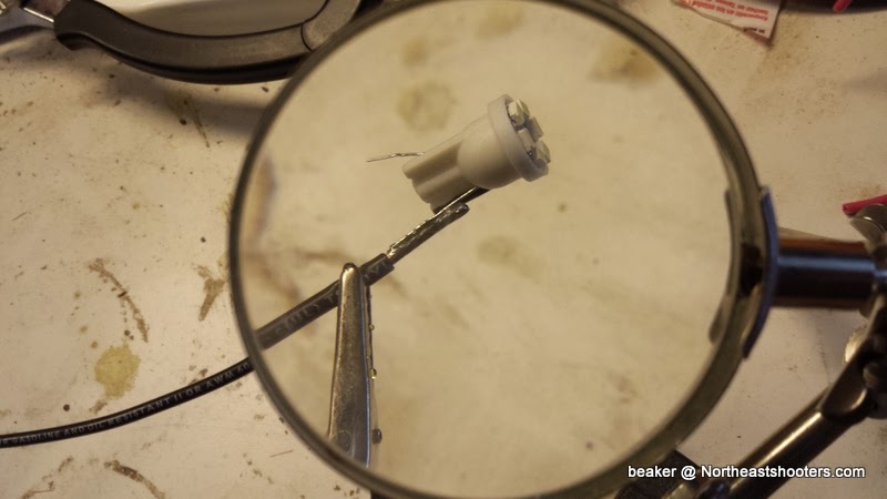
1 RED @ 18" - Strip ONE END 1/2"
1 BLACK @ 18" - Strip ONE END 1/2"
14 Gauge is what I had, but it gives the cord just the right amount of stiffness once it is all shrinked IMO. 16 Gauge would likely be good as well.

Washer
Lowes - pack of 4 - $1.00 - 8mm x 24 is just the right size

Everything to assemble the light.
PressLight_11.jpg


MAKING THE ALUMINUM BODY
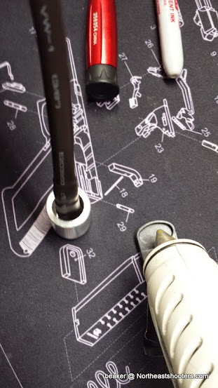
The hardest part is modding the aluminum spacer. If you have a lathe and some stock, you could make this out of Aluminum, Brass, Plastic, or steel if you have the right tooling. I did this using a hand drill and a vice.

I looked through my tools to find something close to the bulb diameter.
PressLight_1.jpg


I used a hand drill, you could use your drill press if you have one, which would actually be better, but mine is buried and I can't get to it at the moment. Plus, I wanted to show how to make it with minimal tools.

Keep in mind that this isn't a valve job on a BMW engine so close enough is good enough.
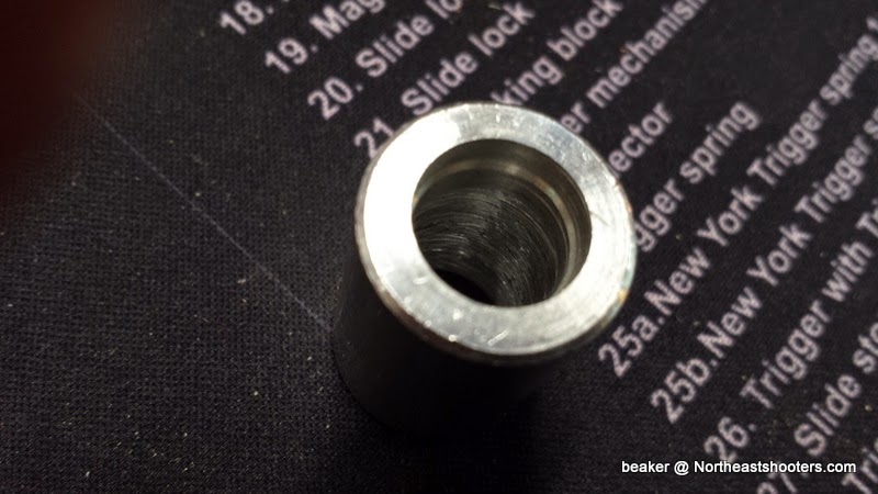
I found that this step drill with its 15/32 diameter step is just perfect, and eats the aluminum spacer like Hillary Clamton on a ... well that's for another time. I put the tape marker on the drill to eyeball the depth. I went full depth on the 15/32 step.
PressLight_2.jpg

PressLight_6.jpg


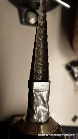
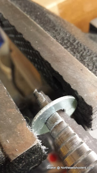
Here is what it looks like after the step drill. Also note high tech corrugated sleeve protector used to clamp the spacer in the vice...
PressLight_5.jpg


While you have the step drill in, open up the washer ID to 3/8". Then turn it around and use the step drill to remove the huge burr on the other side of the washer.
PressLight_8.jpg


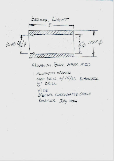
Once you get the bulb end drilled, turn the spacer around and drill it from the back with a 1/2" drill. You have to be careful and stop the drill before you drill into the 15/32" diameter (just shy) per the sketch below. I don't have a picture of the 1/2" drill, it was so blurry it reminded of me of the night I drank way to many Kamikazes and ended up sleeping under a tree. Shudder.

You can probably just drill 1/2" through the spacer and skip the step drill if you don't mind the poor fit around the bulb.
BeakerLightDrawing.jpg


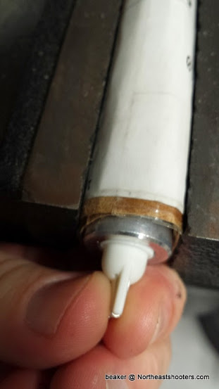
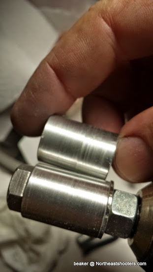
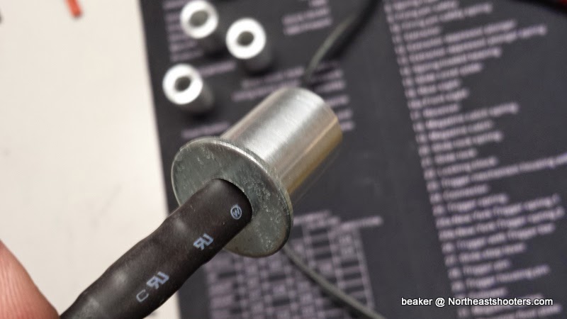
When you are done, it hopefully looks like this.
PressLight_9.jpg

PressLight_7.jpg


Back end with the 1/2" diameter hole.
PressLight_14.jpg


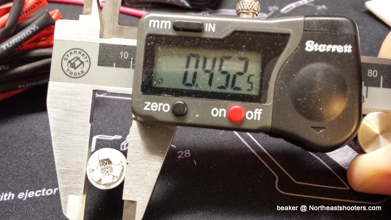
There is just one problem with the spacer. The diameter is 0.750"+ and the diameter of the hole in the tool head is smaller than that. If you have a lathe, no problem, shave off 0.010 or 0.020. I used some hardware I had to make up a holding jig to spin the spacer and used some 100 and 200 grit emory cloth to take off some material on the diameter. It is doable, but be careful.
PressLight_12.jpg

PressLight_13.jpg


The rest will be in additional posts.
 
Last edited:
LED Light Part 2

Part 2 - Solder the bulb and putting the thing together.

Strip about 1/2" off one end of each wire. DO NOT STRIP BOTH ENDS. Tin the wire with a bit of extra solder on the ends.
PressLight_15.jpg

PressLight_20.jpg


Bend the contacts on the bulb out so the are straight and on a slight angle for soldering. Don't over bend them and be careful so you don't break them.
PressLight_16.jpg


PressLight_17.jpg


You need to figure out which contact is + and - as it won't work if they are wired backwards. I use some alligator clips with 12V DC. If it doesn't come on, switch the clips. Once it lights up, use a sharpie to mark the negative side as shown.
PressLight_19.jpg


Carefully solder the black and red wire onto the proper contacts. Make the bulb contact wire is straight before soldering anything, but minimize how much you bend it back and forth. Handle it carefully as you don't want the heavy wires bending the thin contacts around and breaking them. Heat up the pre-tinned wire, put a little new solder on the iron first and when it melts, place the terminal of the bulb in contact and quicky run the iron tip, flowing solder over the bulb contact wire to get it firmly attached. Try not to overheat the bulb contact.

PressLight_1A.jpg


Put a 1 1/4" (3mm) shrink tube over the connections and shrink. Then put another one over the first and shrink so there are two layers. Handle the assembly by the wires by holding them just under the contacts so there is no stress on them.
PressLight_23.jpg


Put the 1 1/4" x 3/8" shrink tube over as shown then shrink it with the heat gun.
PressLight_24.jpg

PressLight_25.jpg


Then put the 2" x 3/8" shrink over that and shrink it. Now the assembly is pretty solid.
PressLight_28.jpg

PressLight_29.jpg


Now slide the 15" x 11/64" red shrink tube over the two wires (this is why you don't want to strip the plug end yet or you will have a very difficult time doing this) and push it down till it hits the end of the 2" x 3/8" shrunk tube. You should have 1.5 to 2" of unstripped wire sticking out of the plug end once it is in position. Shrink the red tube.

Now take the 5" piece of 3/8" shrink tubing and slide it down so it goes over the red, and push it to the bulb as shown and shrink it.
PressLight_31.jpg


You should have something like this.
PressLight_32.jpg
 
Last edited:
LED Light Part 3

Part 3 Final Assembly

Plug the hot glue gun in to warm it up.

If the red and black wires are different lengths, trim the long one so they are the same. Strip about 3/16" (no more) off the end of the wires and retest the assembly to make sure it still works.
PressLight_34.jpg


Install the wire assembly into the aluminum body like so.
PressLight_35.jpg

PressLight_36.jpg


Stand up the assembly on your bench or table like this, as we are now going to inject hot glue into that 1/2" back hole. I leaned the wire to the side to put the nozzle as far down as it could go, the slowly squeezed glue in so it ran down onto the back of the bulb. Make sure the gun is hot so the melted glue is as runny as possible. When it looks like it full, stop squeezing the glue gun and push the wire back towards the center. This is important because it will align the washer off center. It isn't a huge issue if it is off center a bit however. If there is glue bulging up over the top, leave it alone, you can trim it later after it cools down.
PressLight_39.jpg


Fill the other side the same way. Let it cool down for a few minutes. If there is glue bulging up over the top of the body, trim it carefully flush using a sharp knife or razor. I don't have to tell you not to cut through the wires right? [wink]

Once that is done, dry fit the washer to make sure it sits flat. If OK, slide the washer back about 3/4" and get the glue gun. It cools quickly so you have to do this quickly. Squirt a good glob of hot glue around the wire at the top of the aluminum body, maybe around 2/3 around. Then quickly press the washer down hard as centered as you can get. If it oozes out of the center a bit, that is perfect. It's OK to get it on the top of the aluminum body as well.
PressLight_37.jpg


Let it cool and trim any globs of glue around the edges so the washer can sit flat.

Time to put on the connector! If you have more than about 3/16" of stripped copper, trim them down as more than that will stick out of the connector too much. Insert wire, screw down the clamps and you should be good to go.

PressLight_12V_Connector.jpg
 

Attachments

  • PressLight_36.jpg
    PressLight_36.jpg
    31.6 KB · Views: 36
Last edited:
lol, I don't shoot shotguns so I wouldn't have even thought about using an empty shotgun shell!

I just looked up the dimensions, and a 20 gauge shell might work pretty well as a body if you cut it down. and installed the light assembly. I'll have to get hold of one and see how it works out.

Shoulder diameter .673 in (17.1 mm)
Base diameter .692 in (17.6 mm)
Rim diameter .761 in (19.3 mm)
Rim thickness .050 in (1.3 mm)

Damn dude... You don't fawk around!
I just used a 20ga shotshell with the primer pusked out. [smile]

12ga shells are .809 diameter per SAMMI so I don't know if they'd be too big.
 
For reference sake, 20ga is too small for the hole in the LNL-AP but is a nice friction fit for the cheap 1157 bulbs I found on Amazon. http://www.amazon.com/gp/product/B00DVHIZ06
I wrapped the thing in tape to make up the diameter... I think I'll pick up a 12ga shell today.

The LNL also has a bolt head in the center of the shell plate that goes up into the skylight hole so care must be taken in mounting depth for the light.
 
What is the hole diameter on the LNL AP?

If that bulb fits snugly in a 20 gauge shell, it might be a great combination to more easily make a light for a Dillon with a 3/4" center hole.

For reference sake, 20ga is too small for the hole in the LNL-AP but is a nice friction fit for the cheap 1157 bulbs I found on Amazon. http://www.amazon.com/gp/product/B00DVHIZ06
I wrapped the thing in tape to make up the diameter... I think I'll pick up a 12ga shell today.

The LNL also has a bolt head in the center of the shell plate that goes up into the skylight hole so care must be taken in mounting depth for the light.
 
Last edited:
What is the hole diameter on the LNL AP?

If that bulb fits snugly in a 20 gauge shell, it might be a great combination to more easily make a light for a Dillon with a 3/4" center hole.

I'll have to measure it - a quick googling didn't turn it up.
I'll try to get a good pic of the 20ga shell and cheap 1157 also. The bulb logs press into the plastic of a shotgun hull enough to distort the diameter. I'll measure the distortion too... Now WHERE did I put those calipers? :)
 
I went to the range earlier and grabbed a couple of the 20G shells from the barrel. I will see how it fits in the Dillon later today.

I'll have to measure it - a quick googling didn't turn it up.
I'll try to get a good pic of the 20ga shell and cheap 1157 also. The bulb logs press into the plastic of a shotgun hull enough to distort the diameter. I'll measure the distortion too... Now WHERE did I put those calipers? :)
 
Dillon 650 Light using a 20 gauge shotgun shell - works awesome!

Based on jtnf's suggestion to use a 20g shotgun shell, I tried to make a light using the same light assembly and the shell casing as the holder. Works great and much easier than what I did with the aluminum spacer.

Pictures below:

20G_shotshell_Light_1-001.jpg


20G_shotshell_Light_2-001.jpg

Mark the shell at 1" from the end.

20G_shotshell_Light_3-001.jpg

Cut off - I used my miter saw

20G_shotshell_Light_6-001.jpg

Punch out the spent primer with a punch and hammer- those buggers are in there but they come out pretty easy.


20G_shotshell_Light_7-001.jpg


20G_shotshell_Light_8-001.jpg

Drill out the end to 3/8" - I used a step drill, like on the aluminum body and washers


20G_shotshell_Light_9-001.jpg


20G_shotshell_Light_10-001.jpg


20G_shotshell_Light_13-001.jpg

Pull the wire assembly through and attach the connector. There is enough friction between the shrink tubing and the 3/8" hole you probably don't need any hot glue, I put some in just to hold it in place.

20G_shotshell_Light_14-001.jpg


Perfect fit! MUCH EASIER than messing around with the aluminum spacer and free from the bucket at the range!
 
I finally remembered to pick up a few 12ga shells from the range today, and can confirm that they are a perfect fit for the skylight hole in the Lock and Load AP.
And, those cheap-o 1157 LEDs from Amazon are STILL a perfect friction fit... Rather than on the barrel of the base (like the 20ga shell,) they fit on the Outside Diameter of the round PCB on which all the chip LEDs are mounted.
The fit of the 12ga shell is perfect - A nice loose slip fit, with the rim of the shell preventing fall-thru like the 20ga (on the LNL-AP.)
The shell/light assembly even rides up and down on the center bolt happily.
When I put this all together (I'm re-mounting my press today) I'll get some pics.
 
Cool - that is good info, pics good!

I finally remembered to pick up a few 12ga shells from the range today, and can confirm that they are a perfect fit for the skylight hole in the Lock and Load AP.
And, those cheap-o 1157 LEDs from Amazon are STILL a perfect friction fit... Rather than on the barrel of the base (like the 20ga shell,) they fit on the Outside Diameter of the round PCB on which all the chip LEDs are mounted.
The fit of the 12ga shell is perfect - A nice loose slip fit, with the rim of the shell preventing fall-thru like the 20ga (on the LNL-AP.)
The shell/light assembly even rides up and down on the center bolt happily.
When I put this all together (I'm re-mounting my press today) I'll get some pics.
 
Spare LNL bushings show there's plenty of clearance.

I think its safe to say, 20ga if your press is blue, 12ga if red. Any readers have other presses that can be measured?
 
Looks great! what does the bottom of the bulb look like? Just thinking how it would be wired. Inquiring minds want to know. :)

View attachment 110674View attachment 110675View attachment 110676

Cool pressfit of bulb to shell, cool slipfit of shell in skylight hole lifted by the ram, and the 12ga shell rim with the ram retracted.


Sent from my Galaxy S4 using Tapatalk Pro - typos are from the GD auto correct unless they are funny substitutions those I'll take credit for.
 
Looks great! what does the bottom of the bulb look like? Just thinking how it would be wired. Inquiring minds want to know. :)

I'll be making another and photograph it this time.
I've decided I will use high brass this time. The LnL AP central "skylight" hole is filled on every upstroke by the socket head cap screw that holds the shellplate. This means that the light gets partially pushed out of the hole on every upstroke, and the low brass I used gets hung up and does not drop back down by gravity.
This does not effect the amount of light noticeably, but it harshes my mellow and interrupts the Zen of reloading. [smile]


The 1157 bulb base has a metal shell and a plastic bottom plate with two contacts for the (traditionally) two filaments.
I soldered the positive wire to both the contacts on the plastic bottom plate and the negative wire to the metal shell.
I found a great drawing on the intertubes:

1157_base_mm.jpg
 
nice what are you using for a power supply & switch?

I like the clean look.
Hate it when stuff is all kludged together. It works, but so much nicer when it is done right! [thumbsup]
 
nice what are you using for a power supply & switch?

I like the clean look.
Hate it when stuff is all kludged together. It works, but so much nicer when it is done right! [thumbsup]

Not OP, but I used a PS that came with a Netgear 16-port 10/100 switch that I removed from service. Netgear used the same connector too, so it was plug 'n play.
 
I actually have one of these in-line switch/dimmer that works well and adds no bulk. Just a standard 12V DC power supply (many people have extras from old computer equipment)

http://www.ebay.com/itm/360838907406?_trksid=p2059210.m2749.l2649&ssPageName=STRK:MEBIDX:IT


Nice... The proper way to dim LED is by PWM, not merely dropping voltage. I had thought to build something like this but for five bucks its' a no-brainer, even for my tiny little brain.


--Edit:
Same thing, with solder leads rather than barrel connectors:
http://www.ebay.com/itm/Low-profile...ch-for-LED-Strip-Light-Bare-Wire/251612284647
 
Last edited:
LED Light Part 3

Part 3 Final Assembly


Plug the hot glue gun in to warm it up.

If the red and black wires are different lengths, trim the long one so they are the same. Strip about 3/16" (no more) off the end of the wires and retest the assembly to make sure it still works.
PressLight_34.jpg


Install the wire assembly into the aluminum body like so.
PressLight_35.jpg

PressLight_36.jpg


Stand up the assembly on your bench or table like this, as we are now going to inject hot glue into that 1/2" back hole. I leaned the wire to the side to put the nozzle as far down as it could go, the slowly squeezed glue in so it ran down onto the back of the bulb. Make sure the gun is hot so the melted glue is as runny as possible. When it looks like it full, stop squeezing the glue gun and push the wire back towards the center. This is important because it will align the washer off center. It isn't a huge issue if it is off center a bit however. If there is glue bulging up over the top, leave it alone, you can trim it later after it cools down.
PressLight_39.jpg


Fill the other side the same way. Let it cool down for a few minutes. If there is glue bulging up over the top of the body, trim it carefully flush using a sharp knife or razor. I don't have to tell you not to cut through the wires right? [wink]

Once that is done, dry fit the washer to make sure it sits flat. If OK, slide the washer back about 3/4" and get the glue gun. It cools quickly so you have to do this quickly. Squirt a good glob of hot glue around the wire at the top of the aluminum body, maybe around 2/3 around. Then quickly press the washer down hard as centered as you can get. If it oozes out of the center a bit, that is perfect. It's OK to get it on the top of the aluminum body as well.
PressLight_37.jpg


Let it cool and trim any globs of glue around the edges so the washer can sit flat.

Time to put on the connector! If you have more than about 3/16" of stripped copper, trim them down as more than that will stick out of the connector too much. Insert wire, screw down the clamps and you should be good to go.

PressLight_12V_Connector.jpg
Wow. VERY nicely done!
 
Are shadows an issue with the single point of illumination? The KMS setup wraps LEDs around the die, but maybe it's a non-issue if the shadows aren't coming into play until after you've already made it 3/4 of the way through the pull?

Amazon product ASIN B07X7KDSM8View: https://smile.amazon.com/gp/product/B07X7KDSM8/ref=ppx_od_dt_b_asin_title_s00?ie=UTF8&psc=1
Not on the Dillon, you can see very clearly as the light is projected straight down into the cases and around the stuff. No shadows.
 
I decided to play around and try this as well.

For a Dillon 650 toolhead.

I tried a 20g Shotgun shell but it slipped right through. A 12 gauge was too big.

I found a fender washer and drilled it out to act as a lip to keep the 20g shell from dropping through.

Then I cut the shell with a pvc pipe cutter. (live round so no dremel used)

I used a micro usb cable I had laying around and cut it open for the power source. It'll be 5 volts. So now I'm looking for LED's to toss in there.

20210110_135215.jpg

20210110_135239.jpg

20210110_135225.jpg

20210110_135353.jpg

20210110_144438.jpg

20210110_144449.jpg

20210110_144507.jpg

20210110_144648.jpg

20210110_144749.jpg

20210110_144909.jpg
 
I found a 1000 lumen flashlight that is powered by an 18650 3.7V battery.

When I apply the power and ground it lights up. Super bright.

I don't know enough to determine whether it's safe to run this.

I have no idea what this circuitry is and I didn't wire it in. I connected directly to the LED.

A little concerned it will get really hot.

Perhaps I need to wire in a resistor.

Any thoughts from people smarter than me.

20210110_163927.jpg

20210110_164959.jpg

20210110_171132.jpg

20210110_172414.jpg


I never wired this in.
20210110_172505.jpg

20210110_172608.jpg
 
I think it's a CREE XM-L2 judging from pictures.

Normally it's being run from a 3.7 Volt battery and now I'm running it with 5 Volts.

I think I'm over-running the LED and it'll probably overheat, especially since I took away a lot of the metal around it.
I may need to run a resister to it.

Going to go test it now with no resistor.
I’m guessing you can run it with much less power and still be very happy.
I don’t know much about any of this but can’t you run that same LED with say a AA? You’ll get less light but with the proximity to your press you really don’t need much and it should run much cooler.
 
Back
Top Bottom